How many of us in tech now live and die by that stupid “usage remaining” metric? As a solo entrepreneur, I know I do more than ever before. I needed a way to track my usage that didn’t take up real estate on my actual monitor, and I’d been looking for an excuse to play around with an e-ink display. This seemed like a perfect fit. Even better, I got to build my first 3D print file, something else I’d been excited to try.
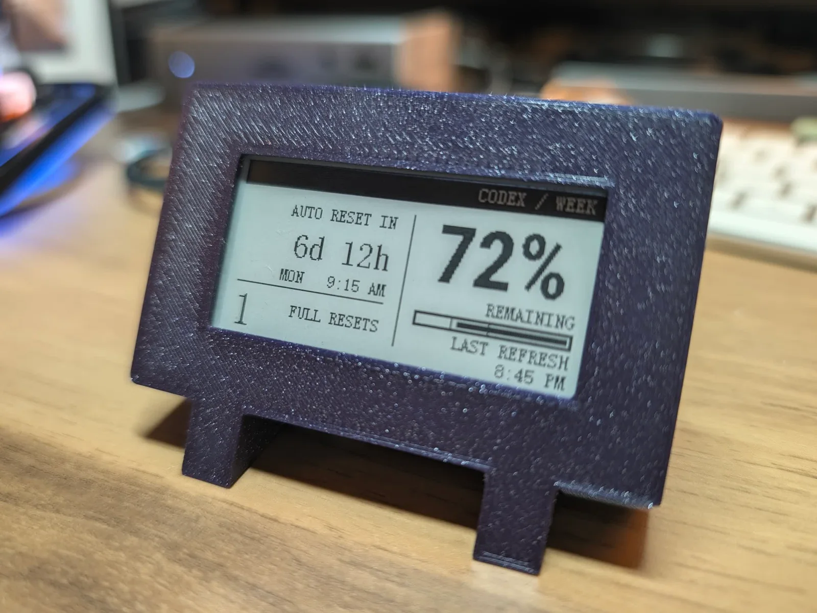
By the end of this build, I’d had a realization: At nearly every developer-marketing job I’ve had, someone has asked why I work so well with developers and DevRel teams. How did I learn to understand that audience so well? Why do I seem to get the way developers think when I’m, very much, a content marketer and not an engineer?
I think this ridiculous little object is the answer.
This was a problem that had a simple solution (a desktop widget) that just wasn’t quite optimal enough for me. So I happily disappeared into the machinery until I got exactly what I wanted. Know anyone else who operates in a similar manner? (Hint: Every dev I’ve ever met.)
If you want to skip the story and build one yourself, the code and firmware are on GitHub, and the enclosure files are on Printables and MakerWorld.
What I actually wanted
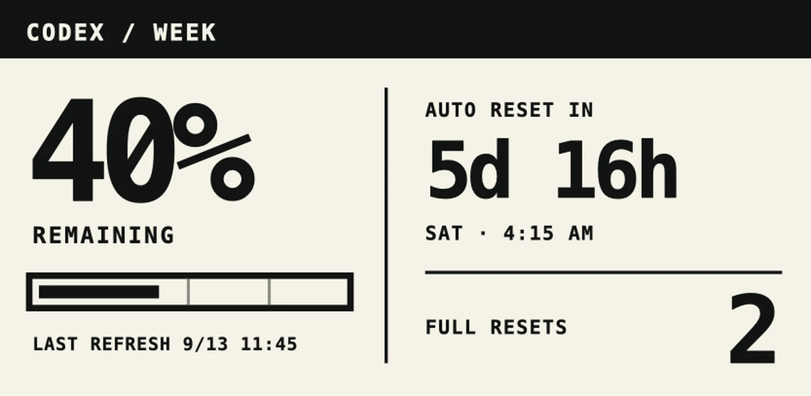
I use Codex heavily enough that the remaining weekly allowance is operational information. I work differently when I have 80% left than when I have 8% and two days before the automatic reset.
The information already existed inside Codex. I’d hover my mouse over usage frequently, often multiple times in an hour, breaking my flow entirely. Truly, it was an offensively small amount of friction. It was also happening often enough to annoy me.
The product brief was:
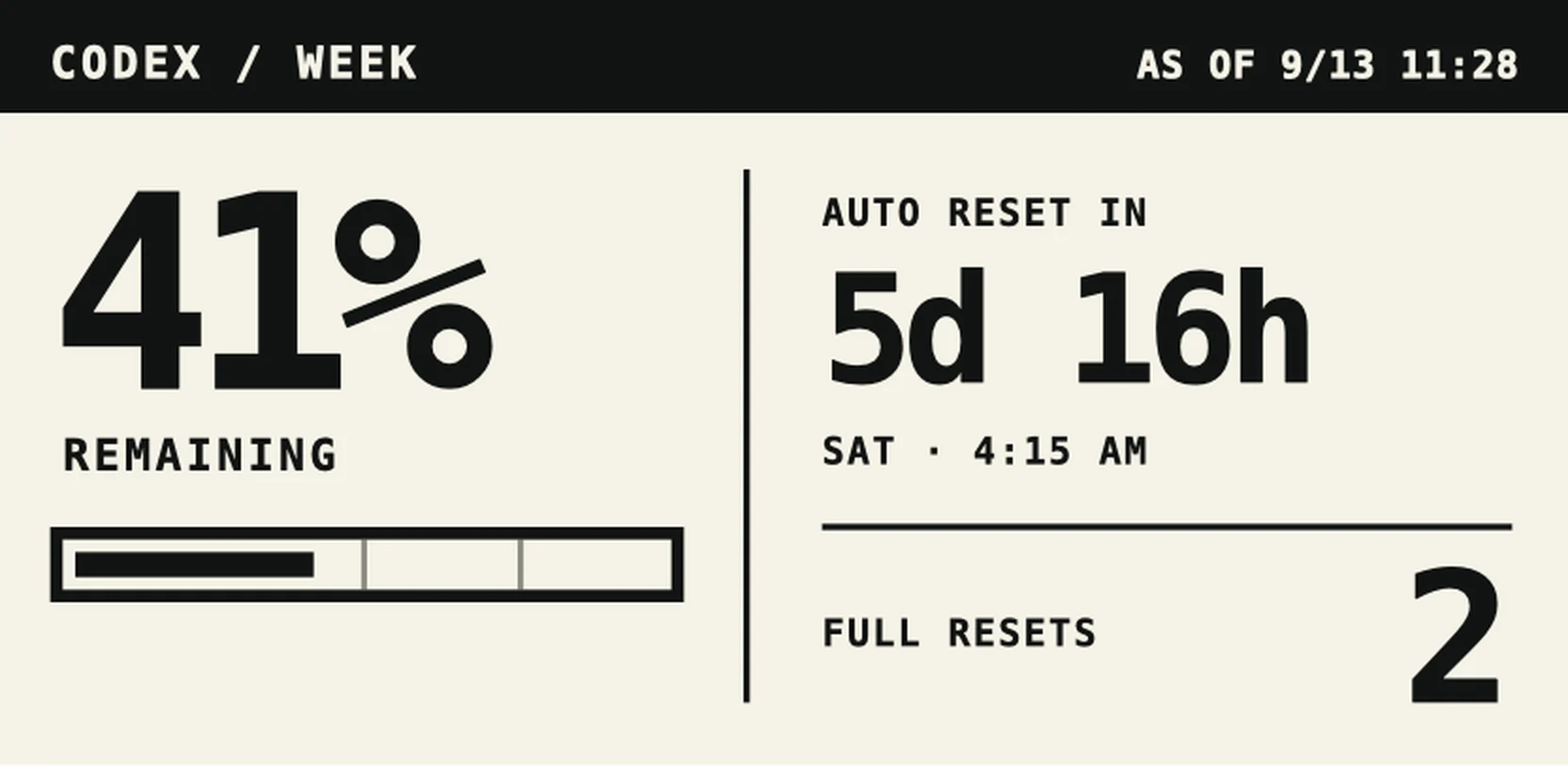
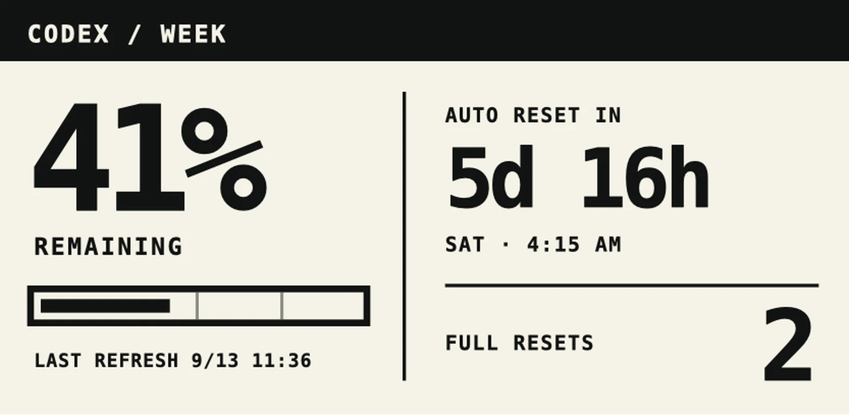
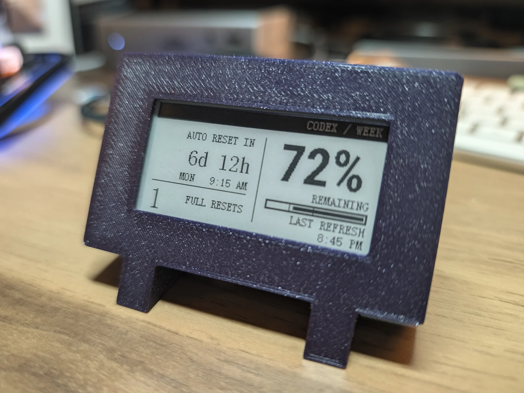
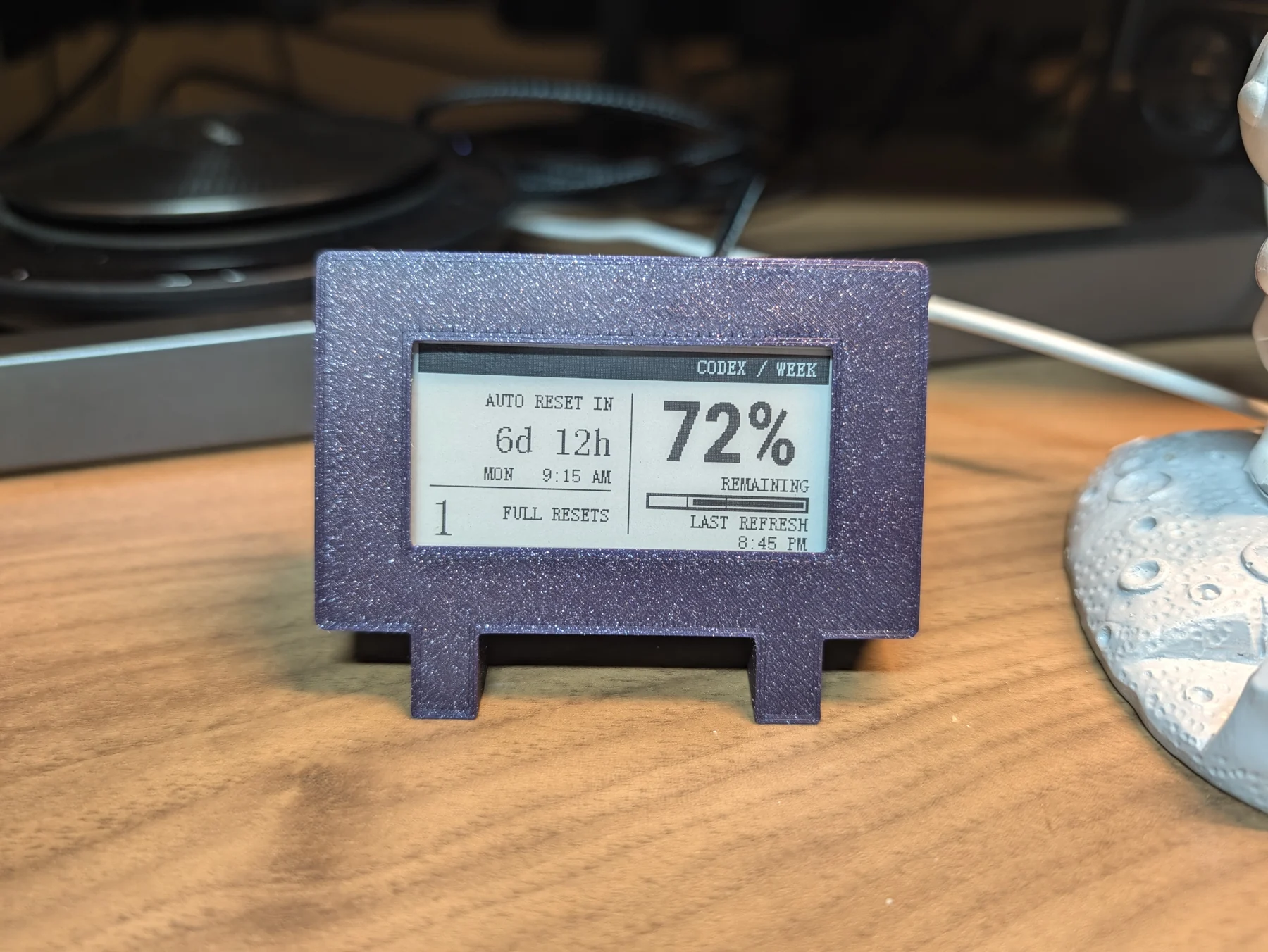
- show the percentage remaining in my seven-day Codex window;
- make the switch from weekly included usage to paid-credit overage clearly when I hit the limit;
- show how long until it resets and when that reset happens in Pacific time;
- show how many full-reset credits I have;
- show the time of the last successful refresh so I can tell if the number is stale;
- be tiny and sit sideways under my monitor without looking like a naked circuit board;
- keep showing the last good data when my laptop sleeps or I unplug the cable.
That last requirement is why e-paper was perfect. It only needs power to change the image. Once the screen has drawn a frame, it stays visible when the device is disconnected.
So, I went to the source of so many previous solutions, Amazon, and found the Elecrow 2.13-inch ESP32 e-paper CrowPanel. It was tiny, black and white, and had a microcontroller built in. I presented it to Codex and started my standard development process, building the content marketer’s version of a PRD, slicing that project into a number of discrete tasks, and spinning up agent after agent to implement each one and check the work of those who came before.
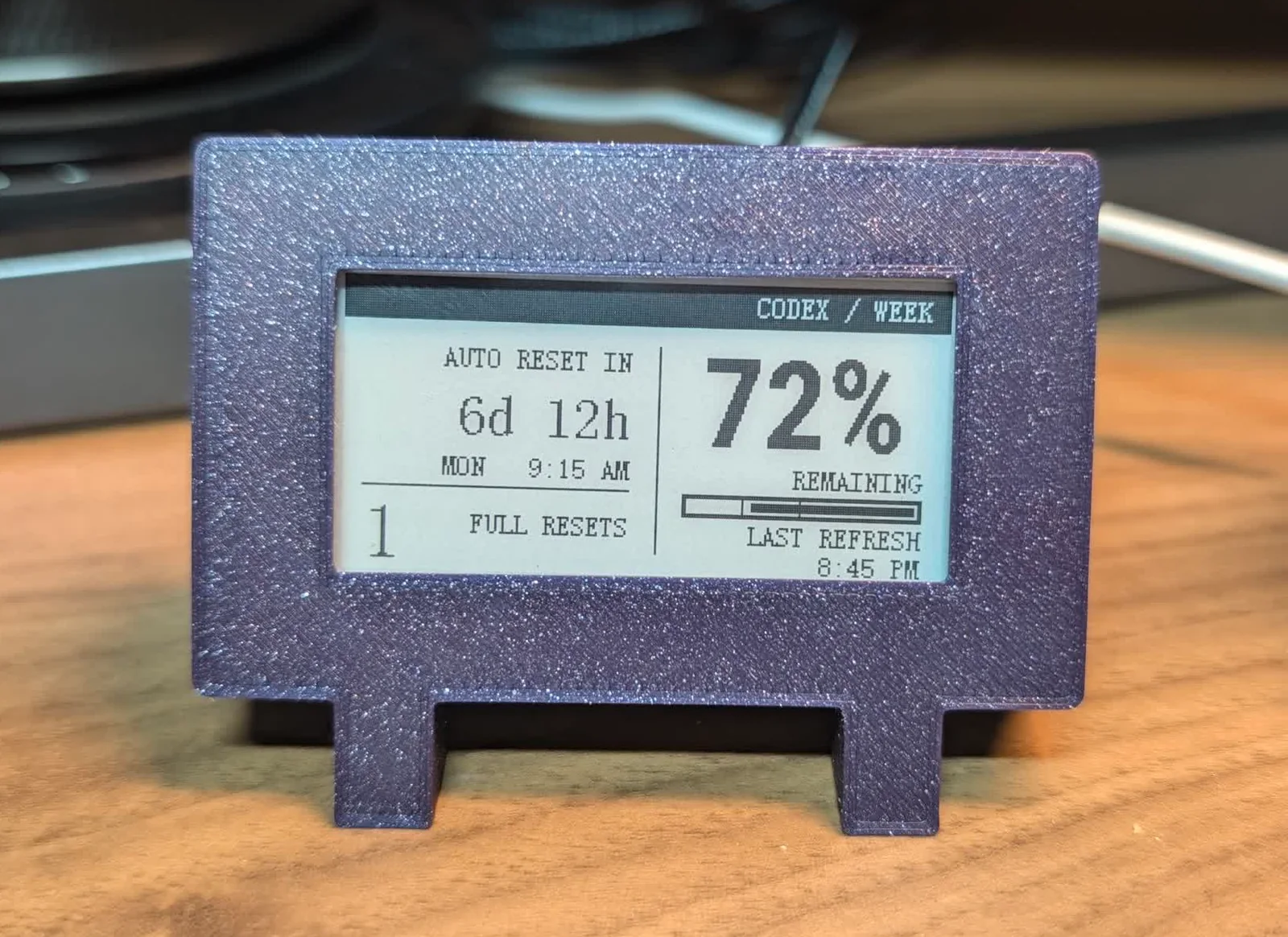
The finished setup has two real jobs
My Mac owns everything private or likely to change. It reads my already signed-in Codex session, selects the weekly usage window, converts the reset time into Pacific time, and sends a very small JSON message over USB.
The ESP32 owns the screen. It receives those display values, draws them, and acknowledges the frame after the physical refresh completes.
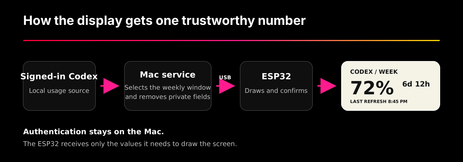
The Mac checks every five minutes. Most changes use a partial e-paper refresh, so the numbers update without the entire display having a seizure. (I found out that e-ink full refreshes are slow and disruptively weird if they catch my attention. Imagine a tiny screen full of musical notation, covered by TV snow at 50% opacity.) After 24 partial refreshes, roughly every two hours, the firmware performs that more noticeable full refresh to clear accumulated e-paper artifacts.
If the Mac sleeps, the service fails, or I unplug the USB cable, the screen keeps the last good frame, which is something cool I didn’t actually realize about e-paper, even though I’ve left my Kindle adrift sans power for months at a time… I should have assumed. LAST REFRESH tells me exactly how old it is.
There’s one main limitation: The project reads the experimental local Codex method account/rateLimits/read. It isn’t a documented public OpenAI API, so it’s subject to change at any time. The parser is strict so that a changed or malformed response stops the update.
What you need to build your own
I built and tested this combination:
- Elecrow 2.13-inch ESP32 e-paper CrowPanel, black and white, 250 × 122;
- a Mac with Codex already signed in;
- a data-capable USB-C port, either on the Mac or through a dock;
- this right-angle USB-C data cable, if you want to use my enclosure;
- eight 3 × 1 mm disc magnets from this mixed magnet set;
- PLA and access to a 3D printer;
- a very small amount of cyanoacrylate glue;
- Git, Node.js 22 or newer, Python 3, Arduino CLI, and libusb.
I used a Bambu Lab P2S and Bambu PLA Sparkle in Royal Purple. The purple sparkle is technically optional, I suppose.
The exact display, cable, and magnet dimensions matter. If you substitute any of them, expect to adjust the OpenSCAD file.
Screen design
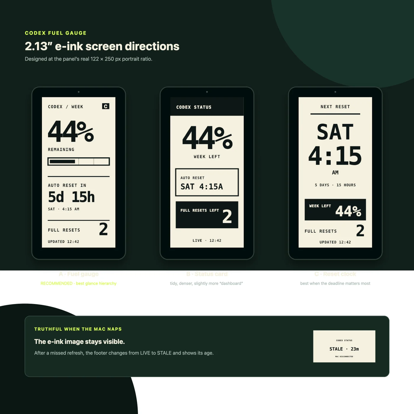
Before I wrote firmware or opened CAD software, I asked for a visual mockup based on my spec. A doodad that sat under my monitor. The first rev was predictably terrible. Several rounds of iteration worked through horizontal alignment, correct information hierarchy, etc.
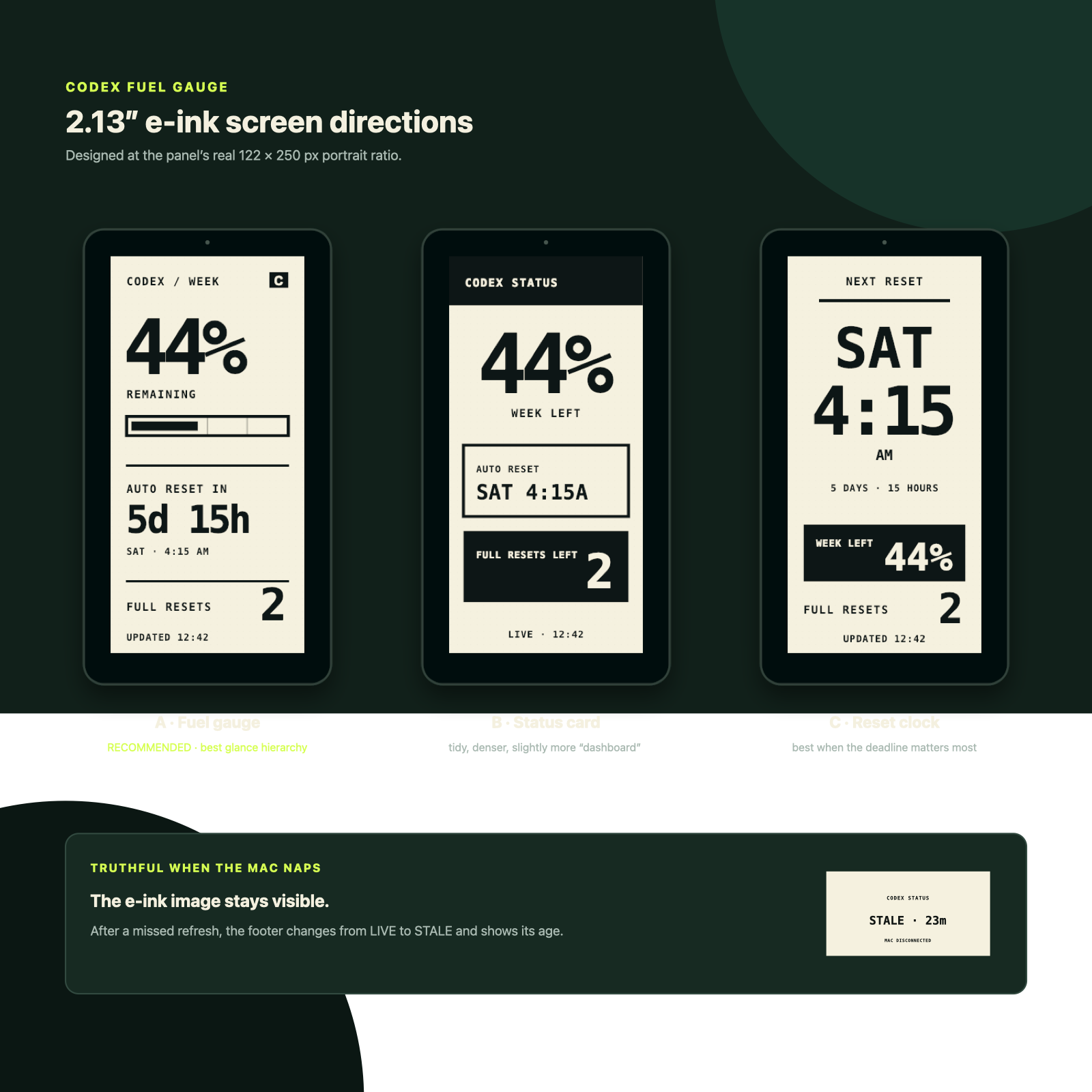
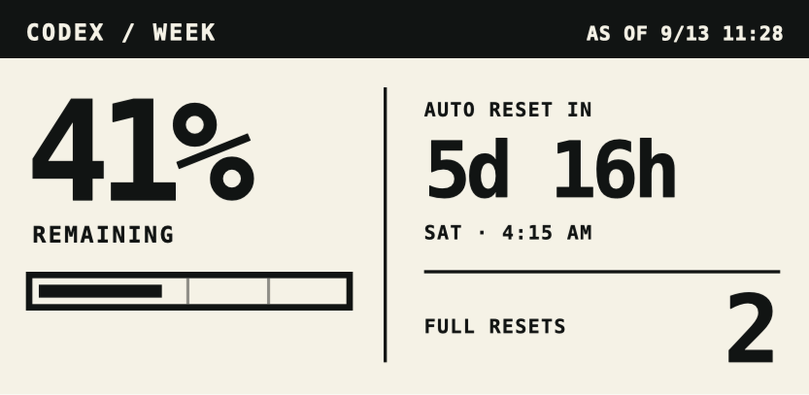
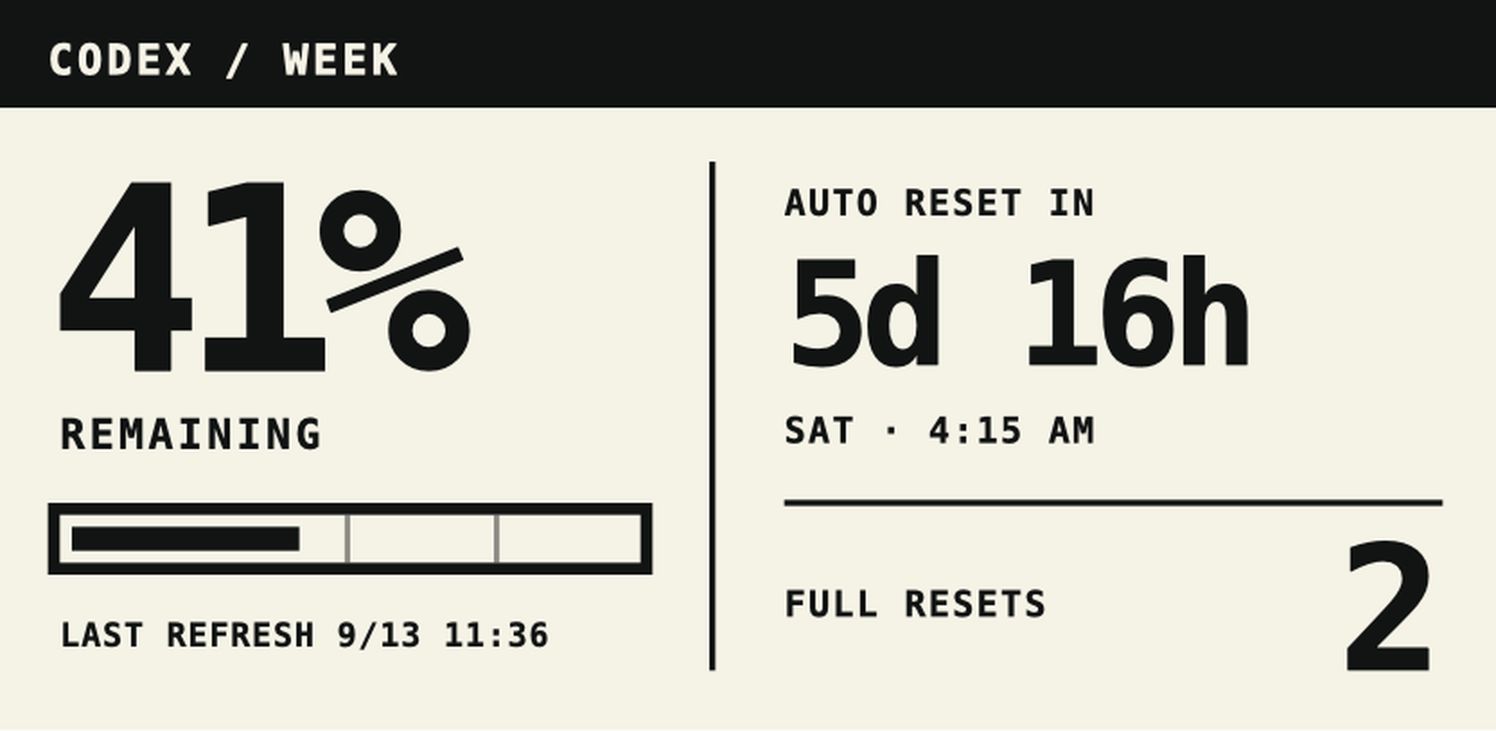
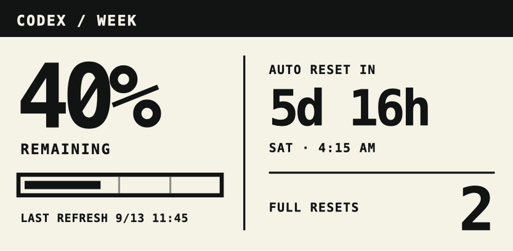
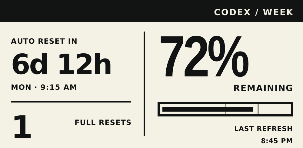
Something I didn’t realize until the very end was that the first hardware redraw had reversed the columns. Elecrow’s landscape driver maps x=0 to the panel’s physical right edge. My browser mock treated x=0 as the left edge, and I carried that assumption straight into the firmware. The thing I kept calling the “left column” appeared on the right side of the device. I was too busy fighting a broken percent sign to notice that I had also built the final screen backward.
This wasn’t a conscious design pivot. It was a bug I liked. The physical layout worked, so it stayed. The final firmware uses a generated Roboto Condensed Bold bitmap for the large percentage and the reset countdown.
Build and flash the firmware
The current instructions live in the GitHub README, which is where you should look if these commands and the repository ever disagree. Technology tutorials age like produce.
Clone the project:
git clone https://github.com/LindsayB610/codex-usage-desk-display.git
cd codex-usage-desk-display
The preparation step fetches the Elecrow driver files from a pinned commit, verifies their SHA-256 hashes, and applies the waveform patch I physically tested. Elecrow’s repository did not include a redistribution license when I built this, so the vendor files are fetched.
The helper checks for the expected USB bridge and verifies that the target is an ESP32-S3 before it writes anything. It also refuses to choose if multiple matching boards are attached.
Install the Mac updater
You can test the host side before installing the background service:
npm test
npm run snapshot
npm run preview -- /tmp/codex-usage-preview.svg
The project has no npm dependencies. snapshot reads the local Codex data and prints the exact privacy-minimized object that would cross the cable. preview renders the same state as a 250 × 122 SVG without touching the physical display.
The repository includes a Mac installer. Run node scripts/install-macos.mjs --dry-run to inspect the paths, then node scripts/install-macos.mjs to install the dependencies, private config, and per-user launch agent. The service starts at login, stays alive, and retries after Codex or USB failures. For paid-credit metering, set paidCreditFullBalance in the private config using the README instructions.
These are the two most useful checks when something seems stale:
cat "$HOME/Library/Application Support/Codex Usage Desk Display/health.json"
launchctl print "gui/$(id -u)/com.example.codex-usage-display"
status: "displayed" means the firmware acknowledged the exact snapshot after drawing it. This is the check I care about: the Mac can say it wrote bytes all day, but the screen has to confirm the frame.
Then the tiny screen needed a tiny house
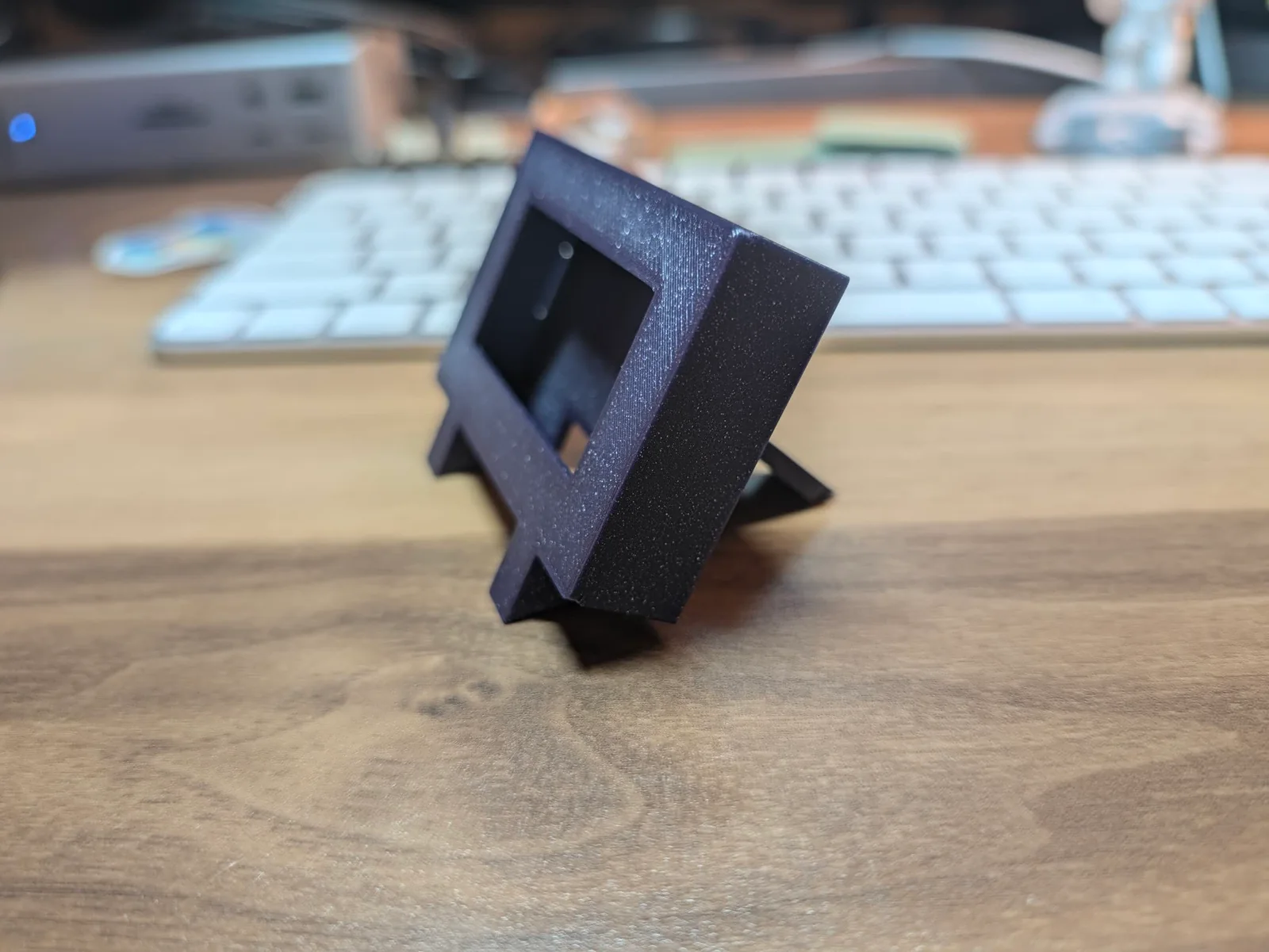
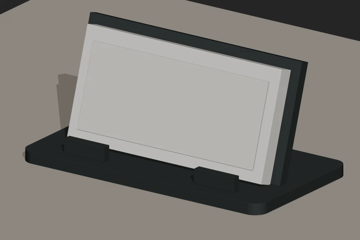
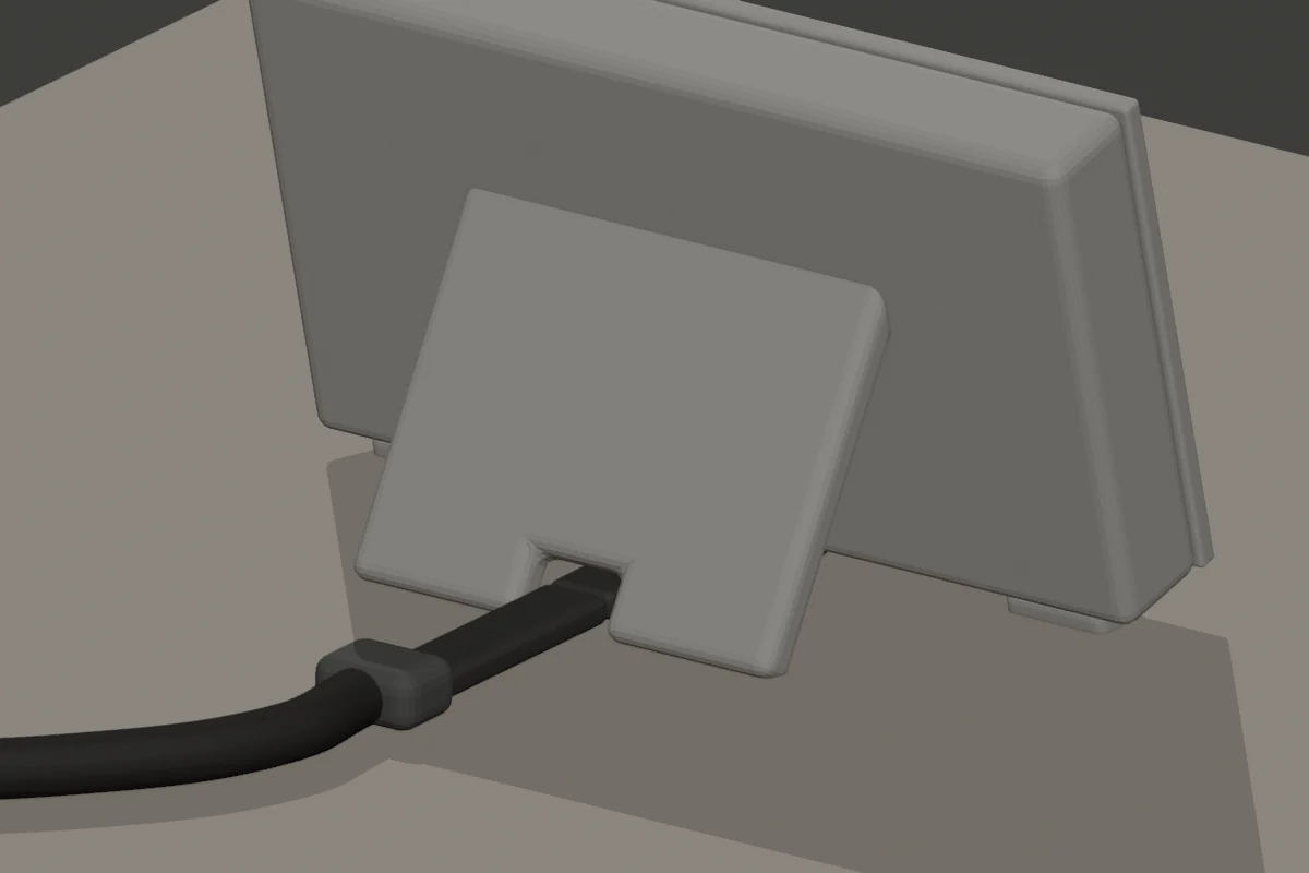
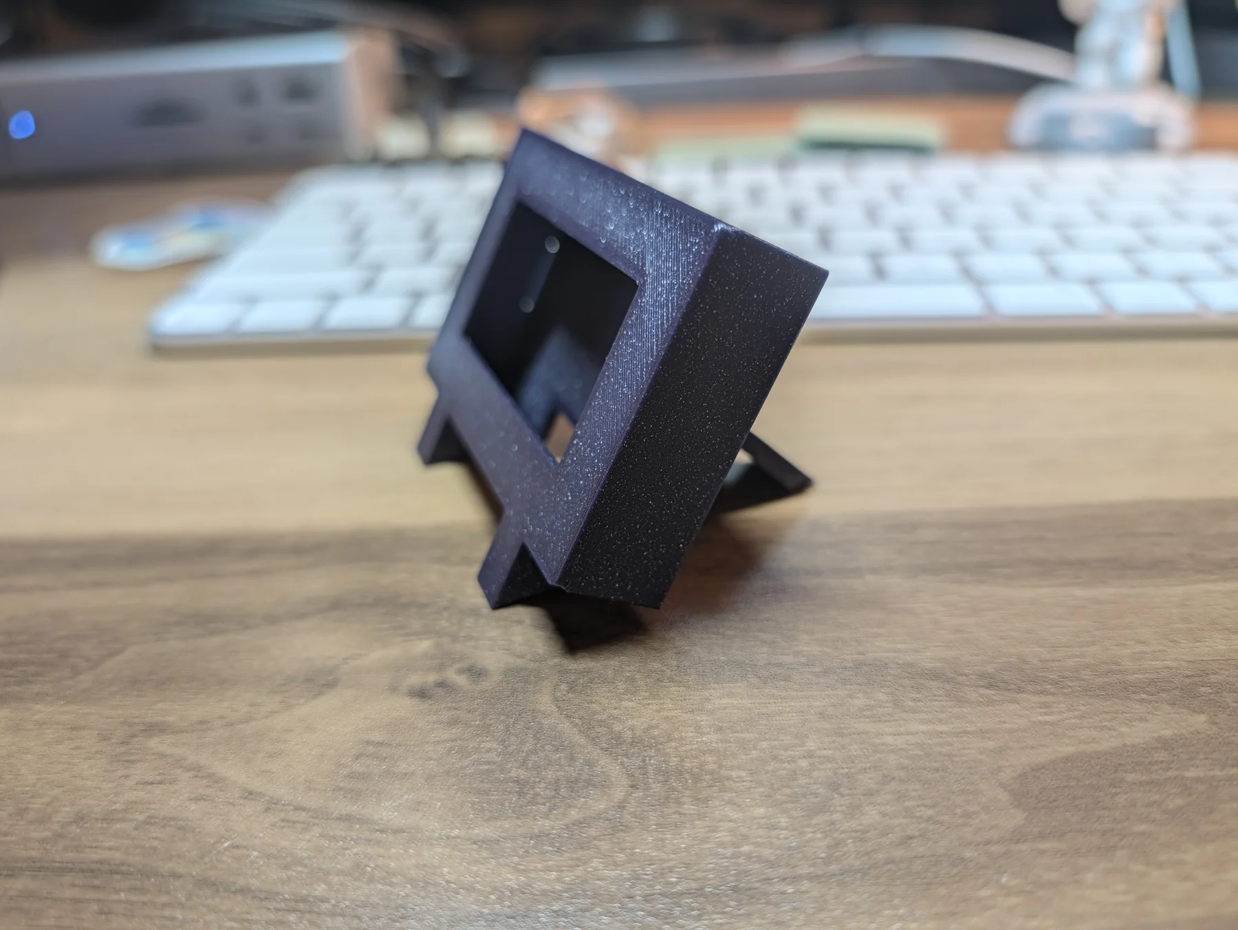
The bare panel worked but I wanted a lean picture frame style housing with the white plastic hidden, an uninterrupted front face, a slight backward lean, and a right-angle cable disappearing through the bottom and out the back. I had a Bambu printer, a stupid variety of filament, and no particular desire to learn Blender well enough to model the thing manually.
I used OpenSCAD. That let me model the enclosure from actual measurements, generate each part, check for intersections, and revise the geometry.
I also found a seven-inch e-ink case by Vladimir Waas on Printables. Its clean picture-frame face and removable rear leg became the aesthetic starting point. I rebuilt the enclosure for this much smaller board, a centered active-screen opening, magnetic rear cover, and bottom cable path. The enclosure files use the same CC BY-SA 4.0 license as the source model.
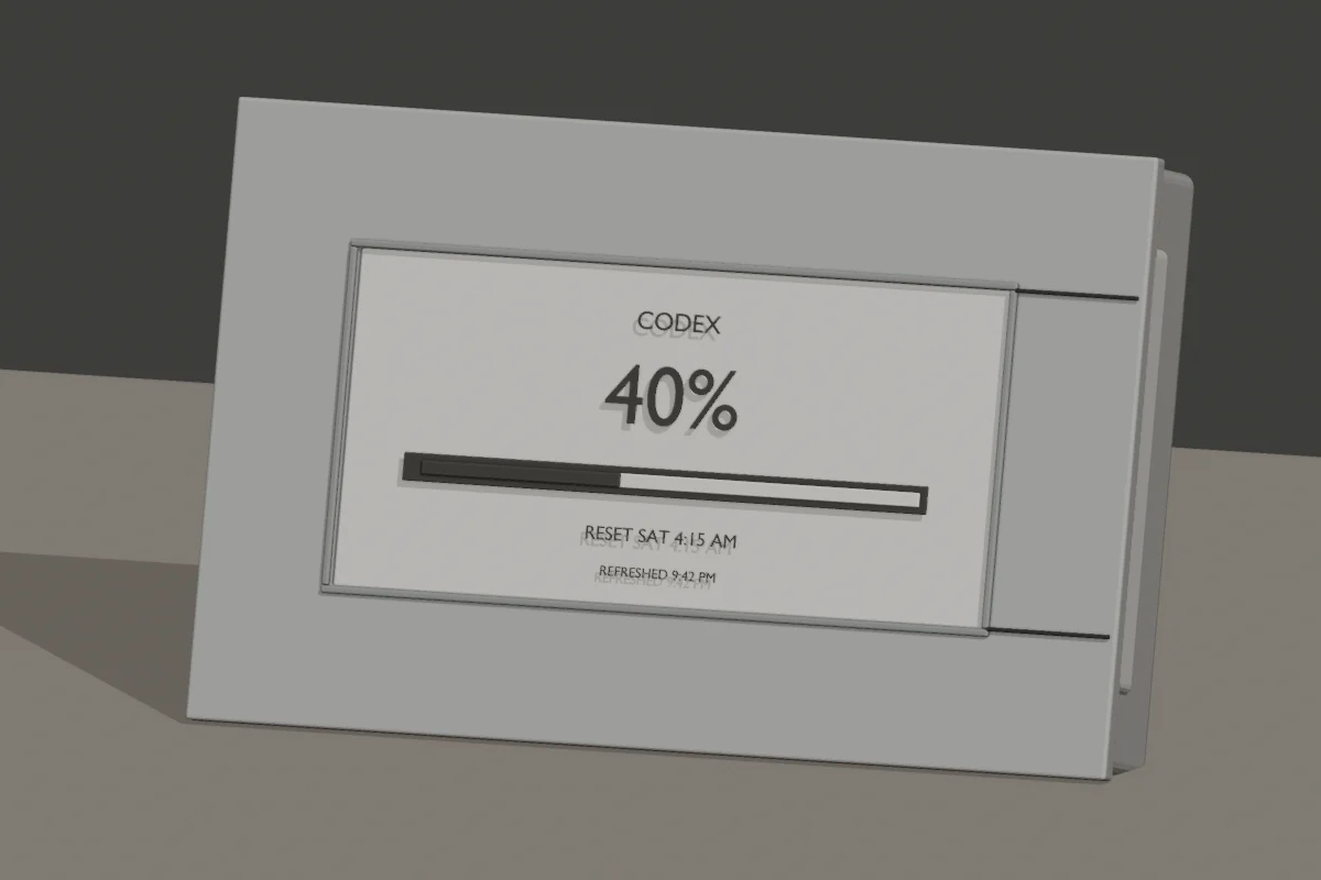
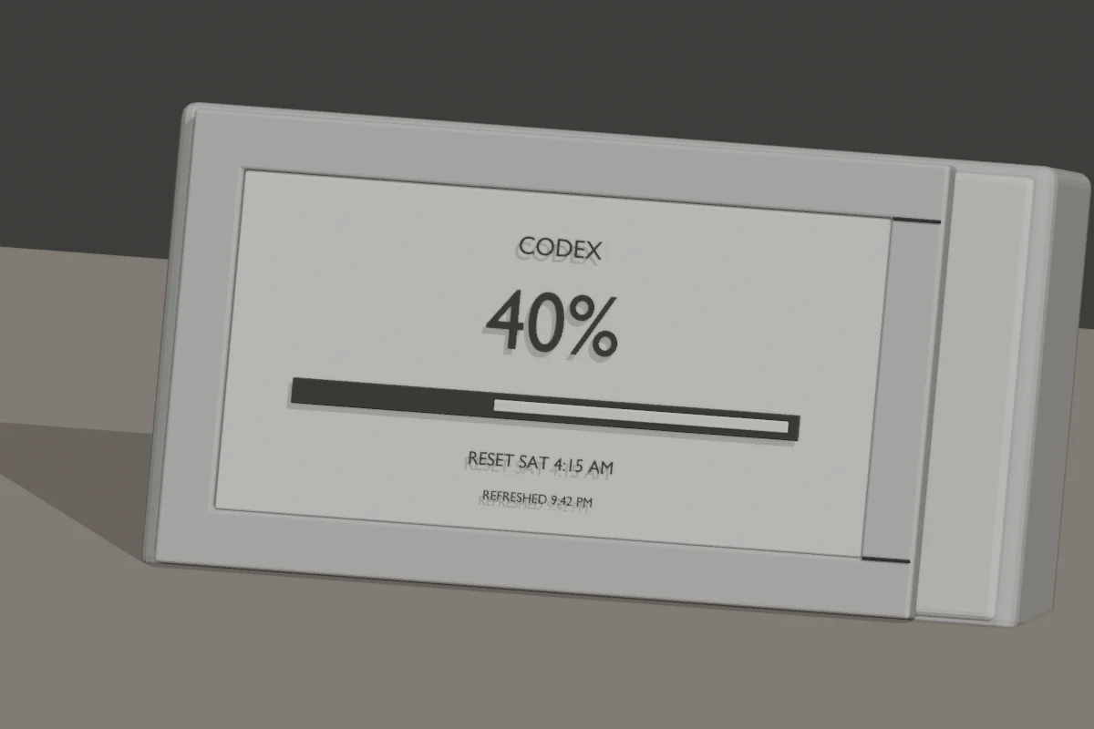
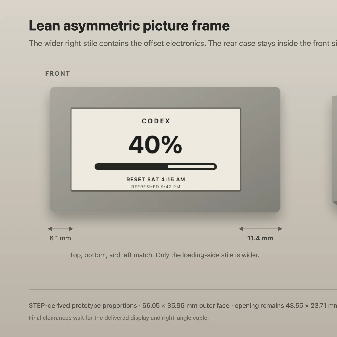
The early concepts wandered from an easel to a rounded retro cassette to a slimmer frame. One attempt kept the bezel narrow by letting the board housing protrude behind one side. That produced a weird shoulder on the right.
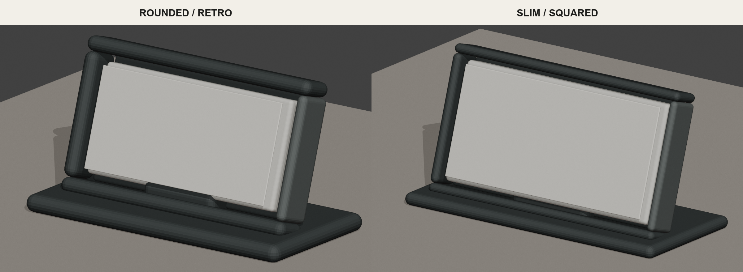
The final front is simple: equal widths all the way around and an opening aligned to the active e-paper area so none of the white housing shows. When the first physical version came off the printer, it was much tinier than I had pictured. That made the giant early bezel feel even more ridiculous and confirmed that the frame needed to get out of the screen’s way.
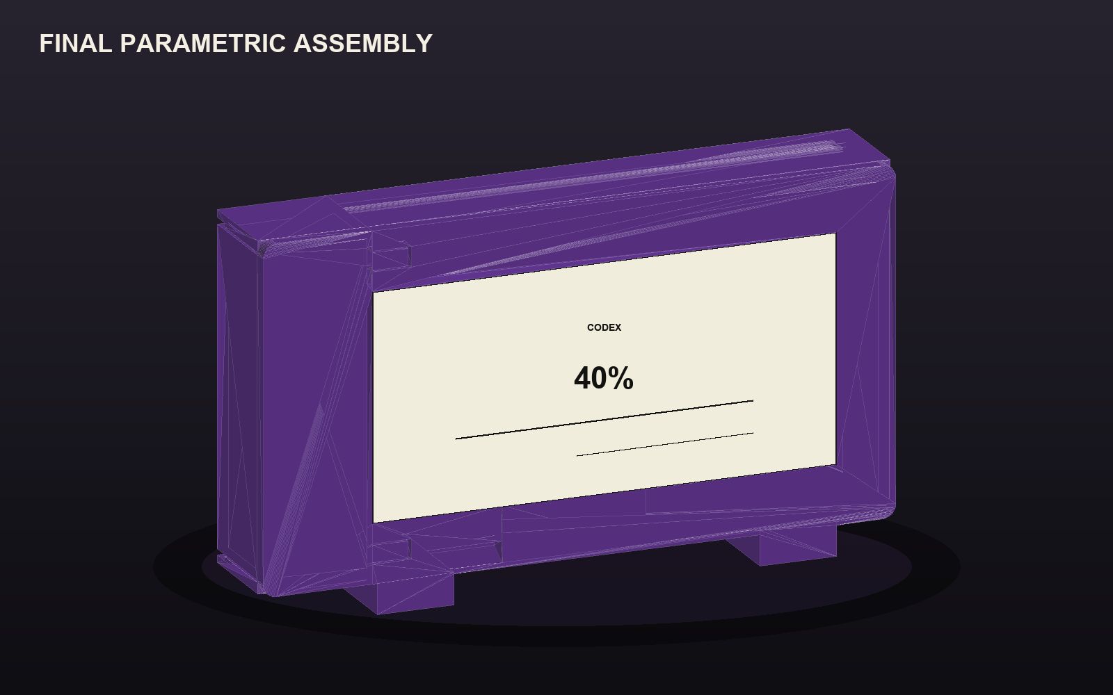
Four prints, one flying latch, and a lot of caliper data
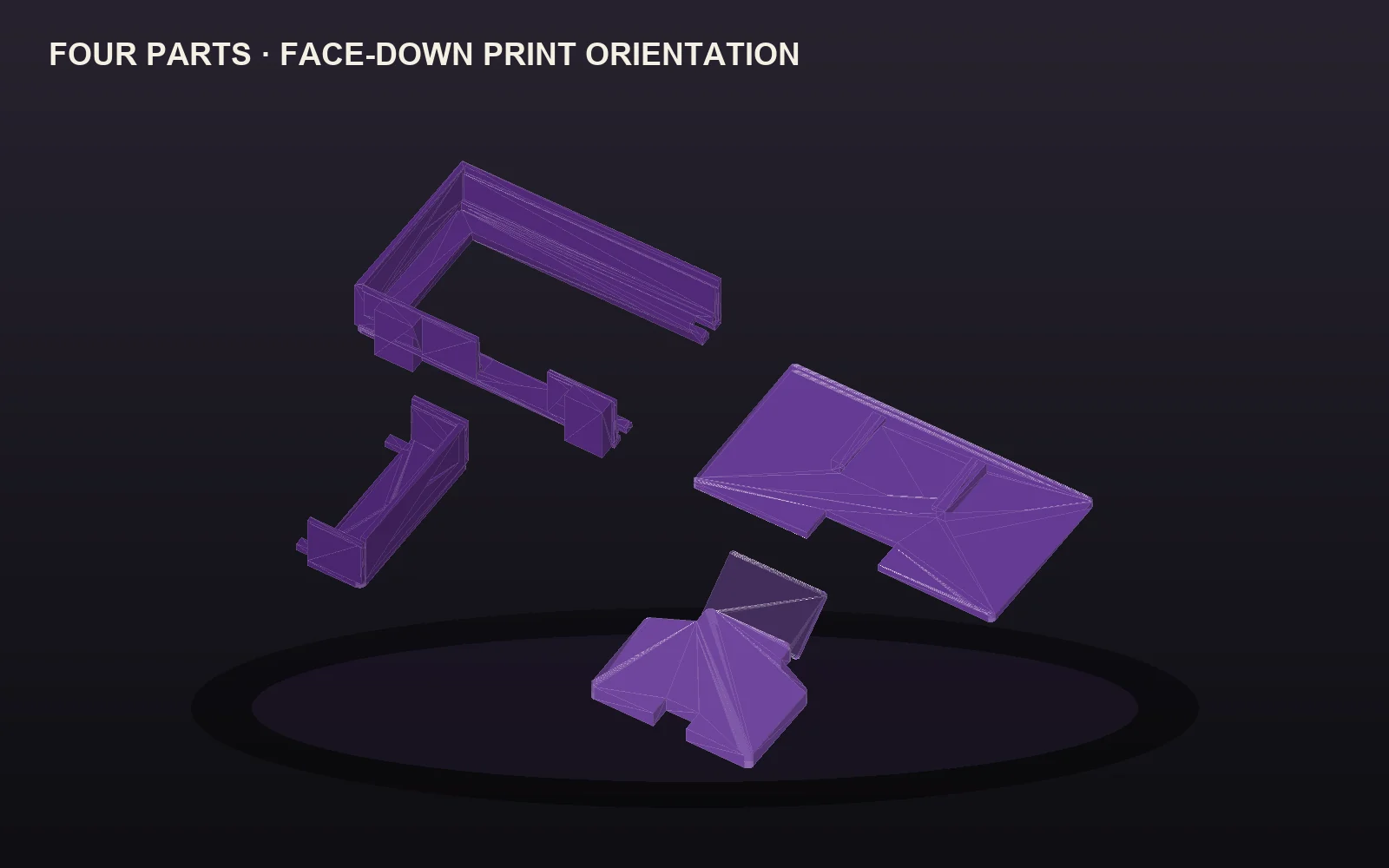
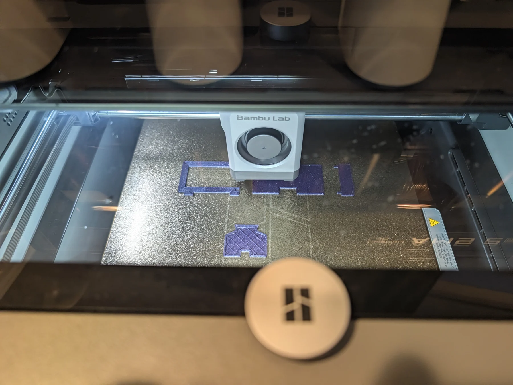
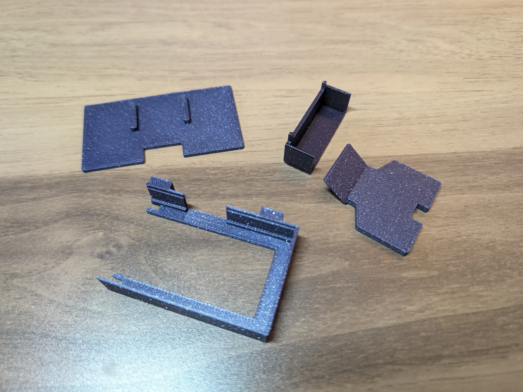
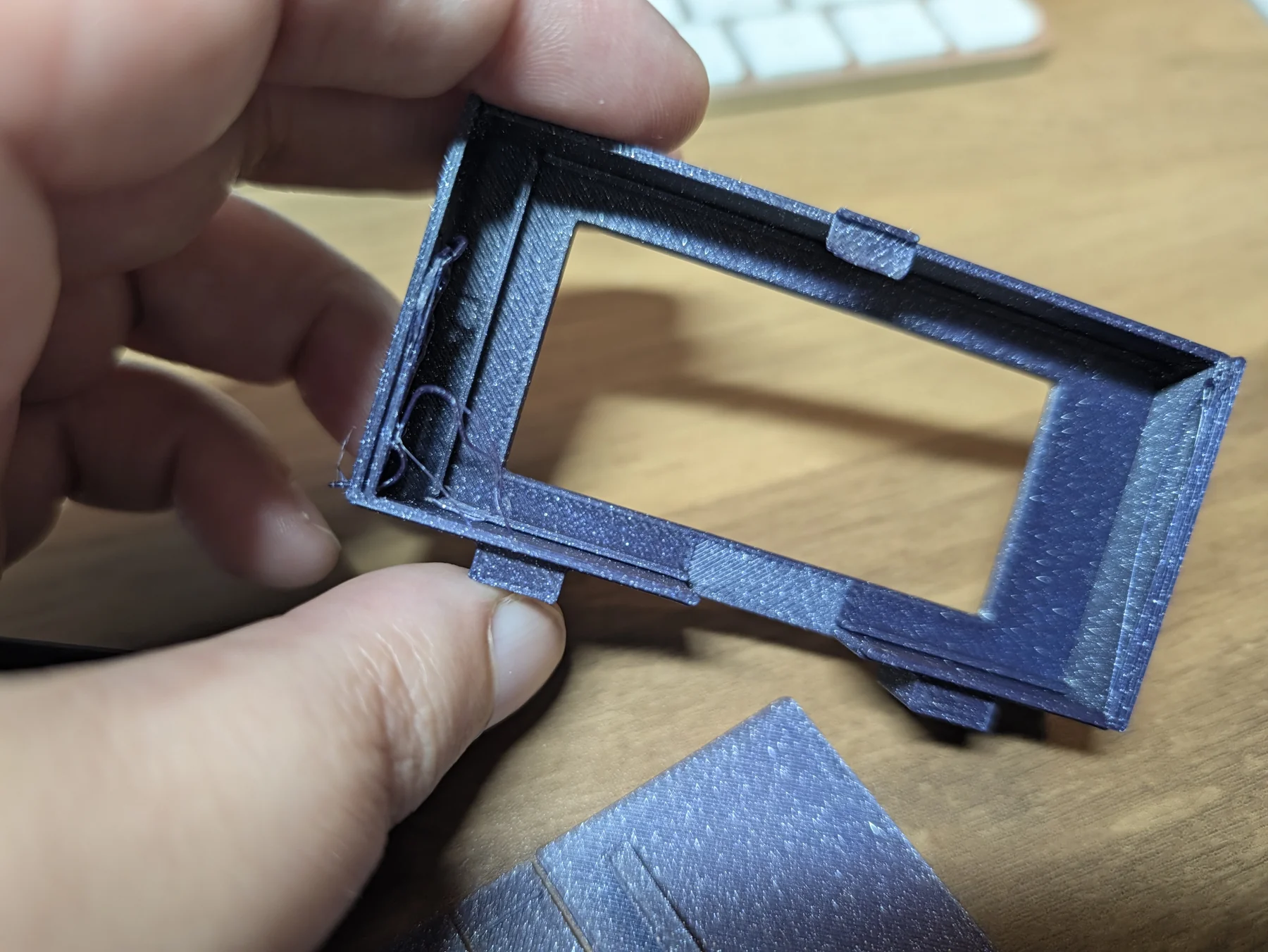
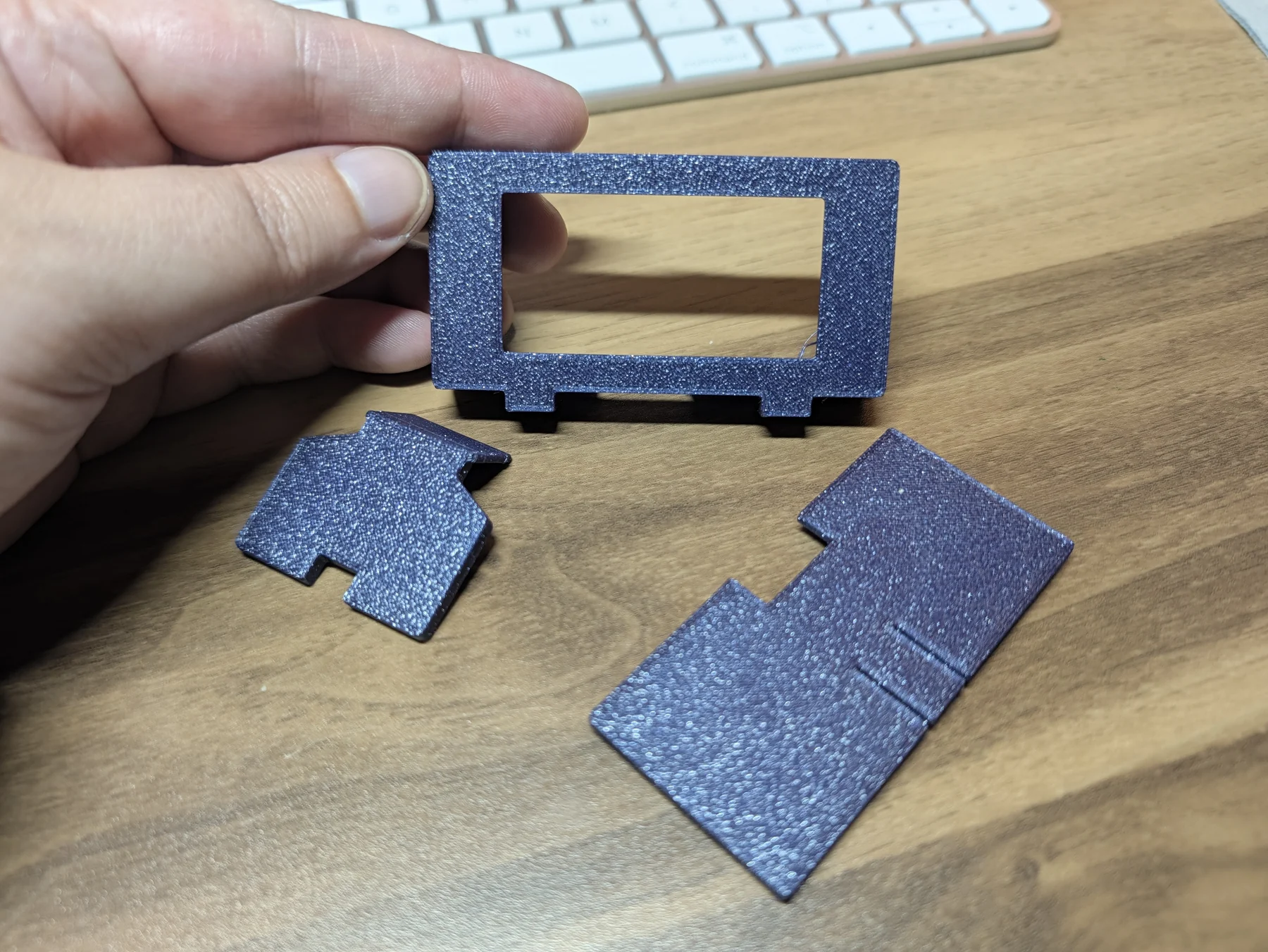
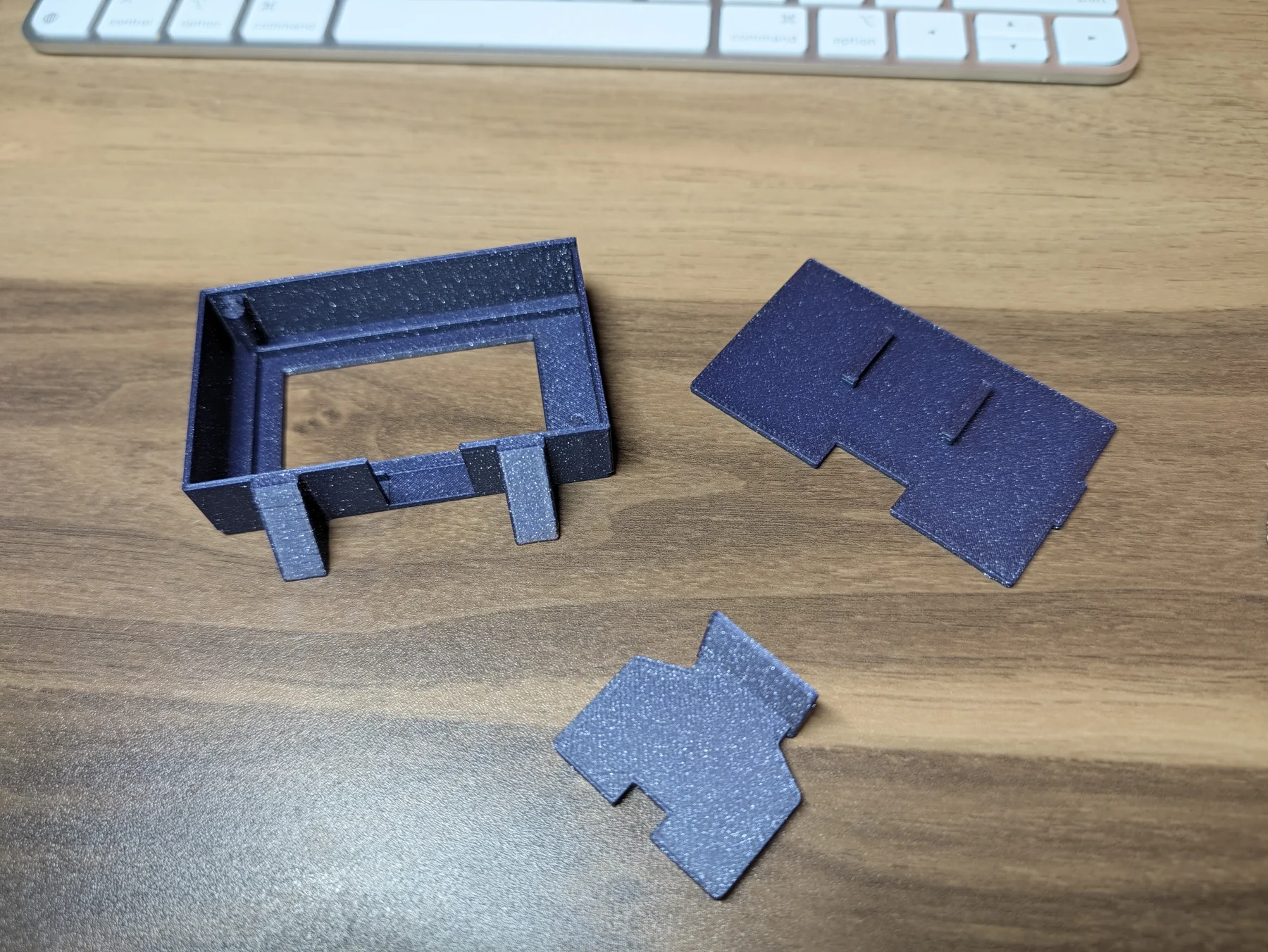
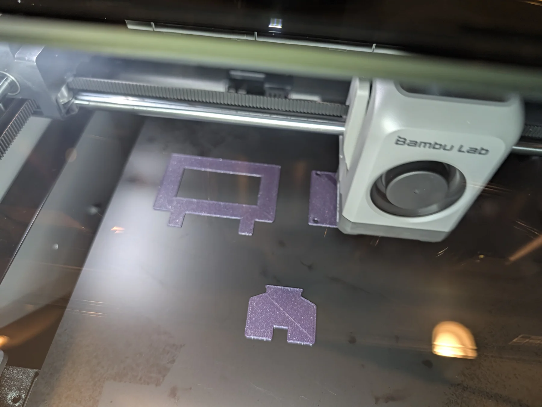
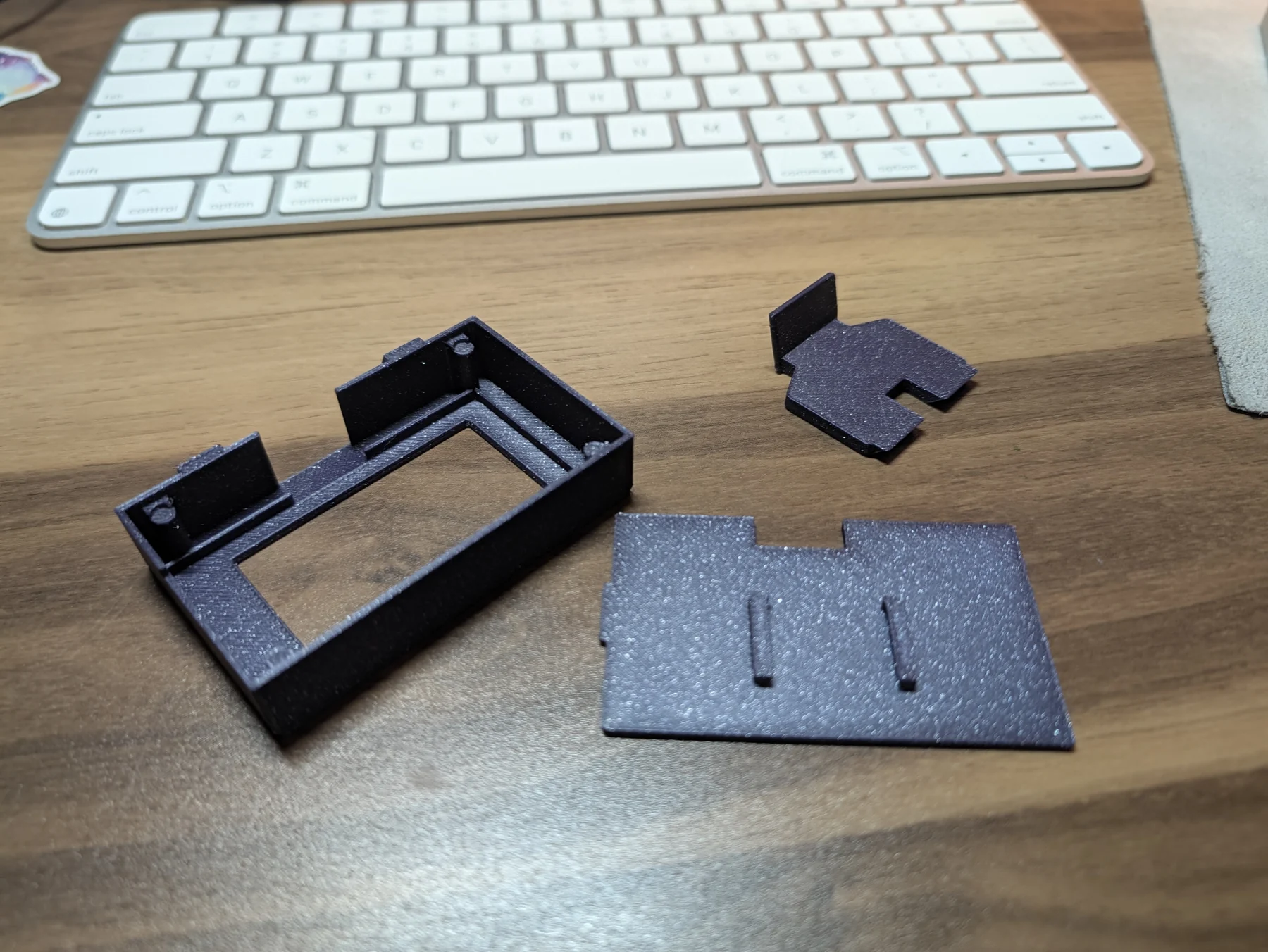
The first print was four pieces: front frame, backplate, removable side stile, and rear leg. The pieces fit together beautifully. They also had almost nothing keeping them together. If I picked up the doodad, it disassembled itself with remarkable alacrity.
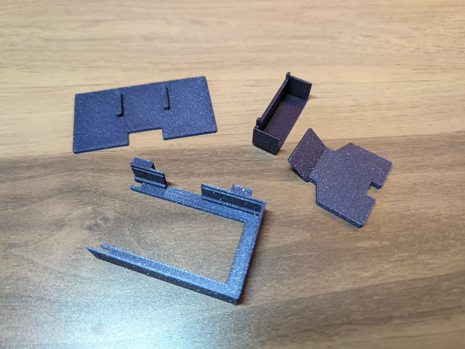
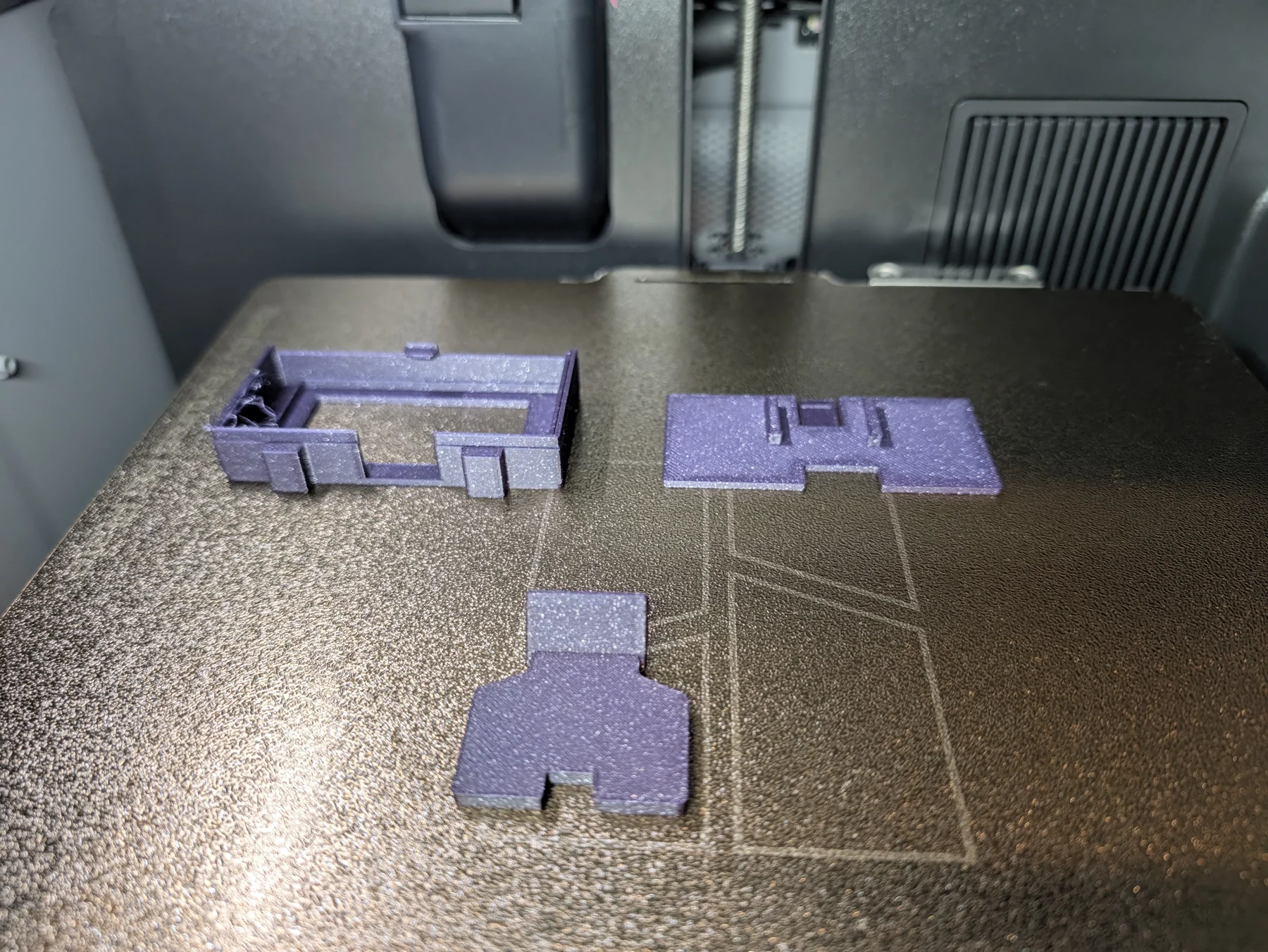
The second version made the front frame one continuous piece, balanced the bezel, and integrated the side into the back structure. It also included a thin printed latch, an idea that never should have been attempted with PLA. The latch blocked the backplate’s insertion path. When I tried to flex it, it snapped off and flew somewhere into my bookshelves, likely never to be seen again. Back to the drawing board.
A 3D build apparently wouldn’t be complete without some spaghetti, so I threw that in for the karma.
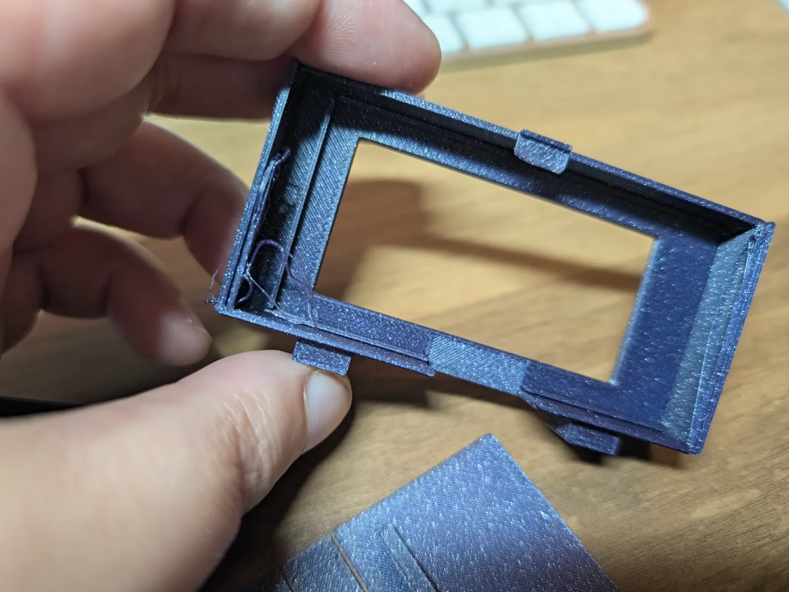
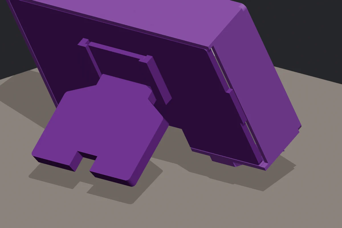
That version leaned forward instead of backward, mostly because AI. The front feet were also still flat in this design, so even a correctly angled leg would have left the frame fighting the desk.
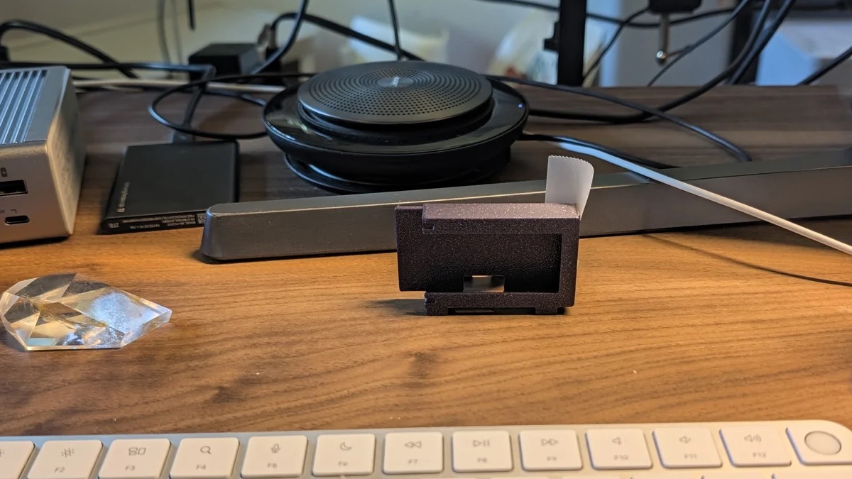
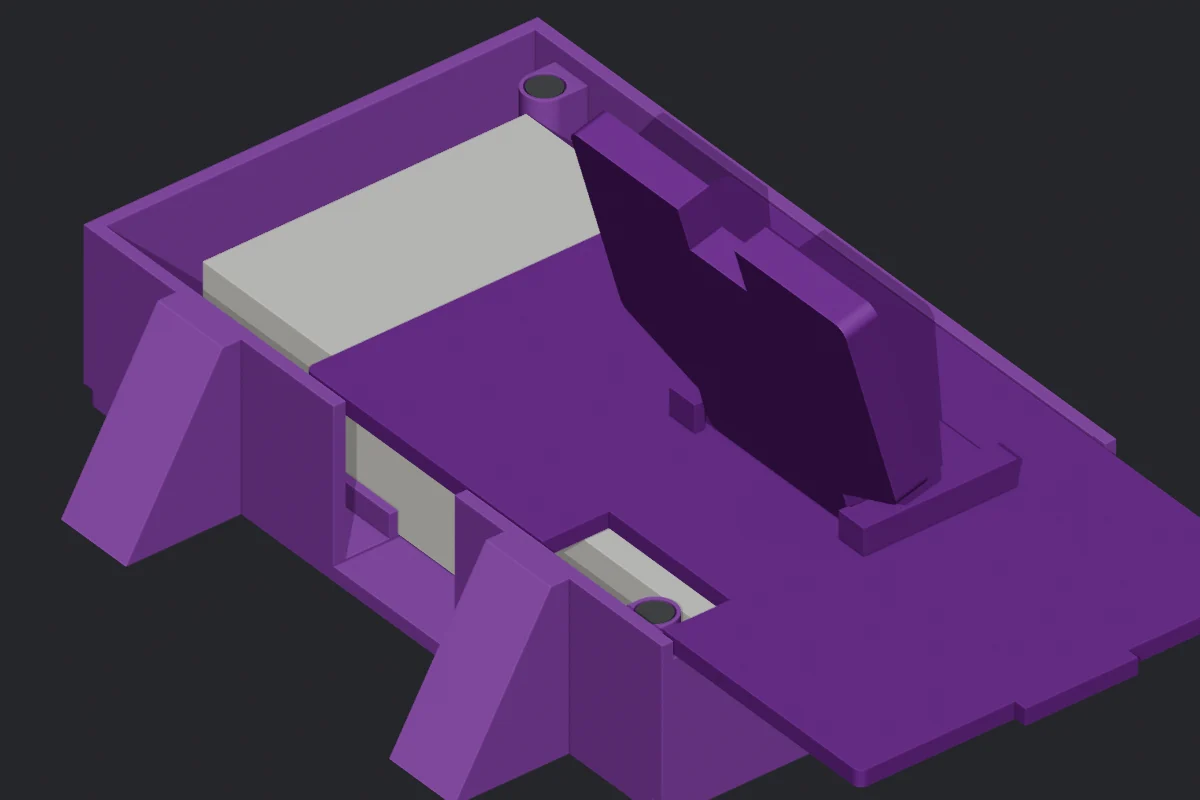
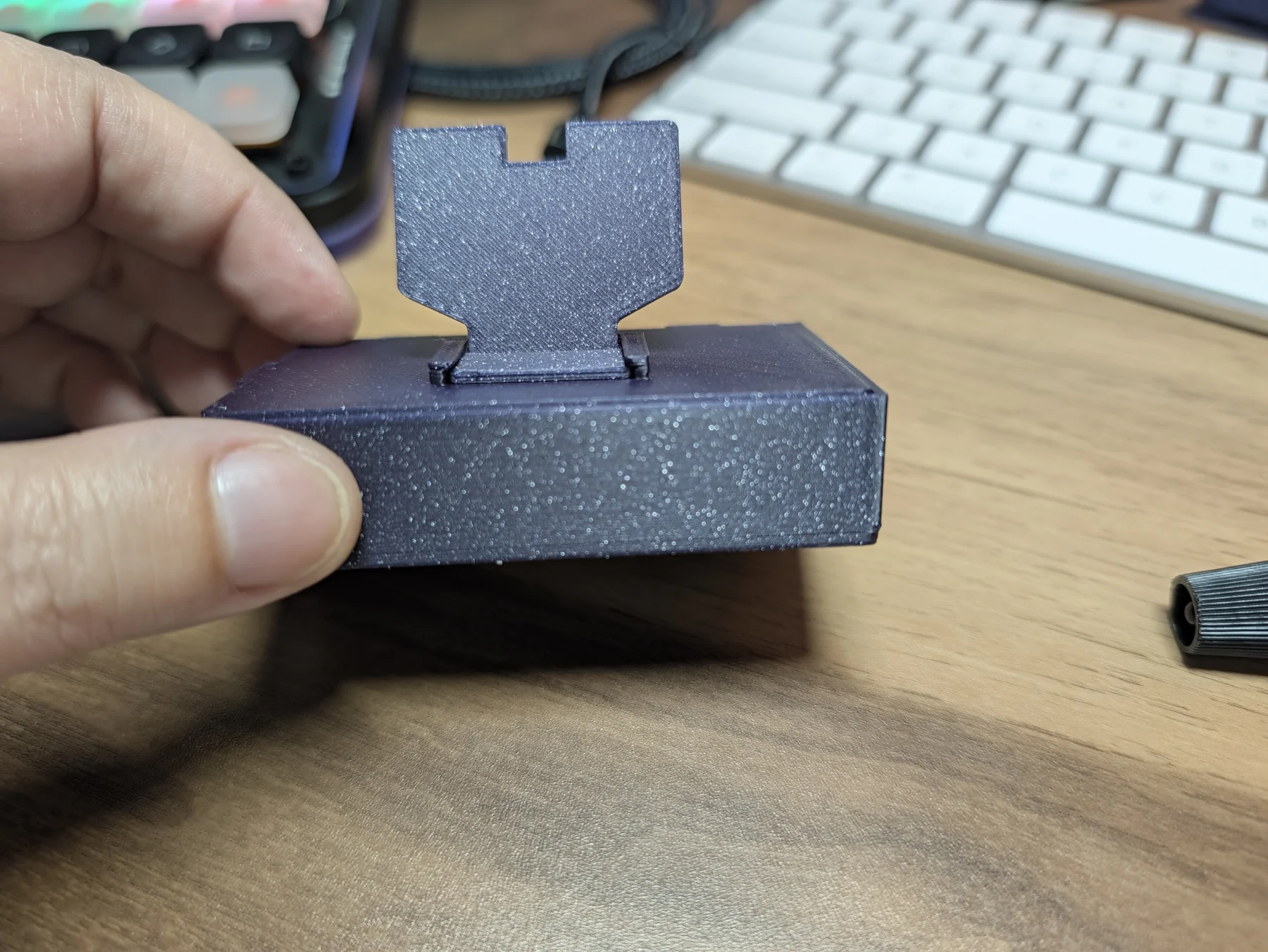
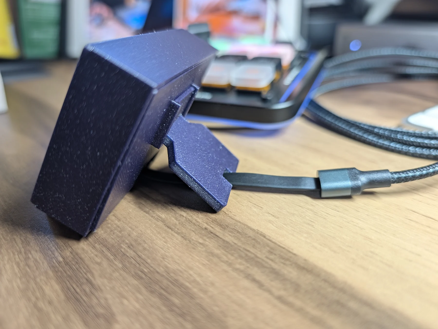
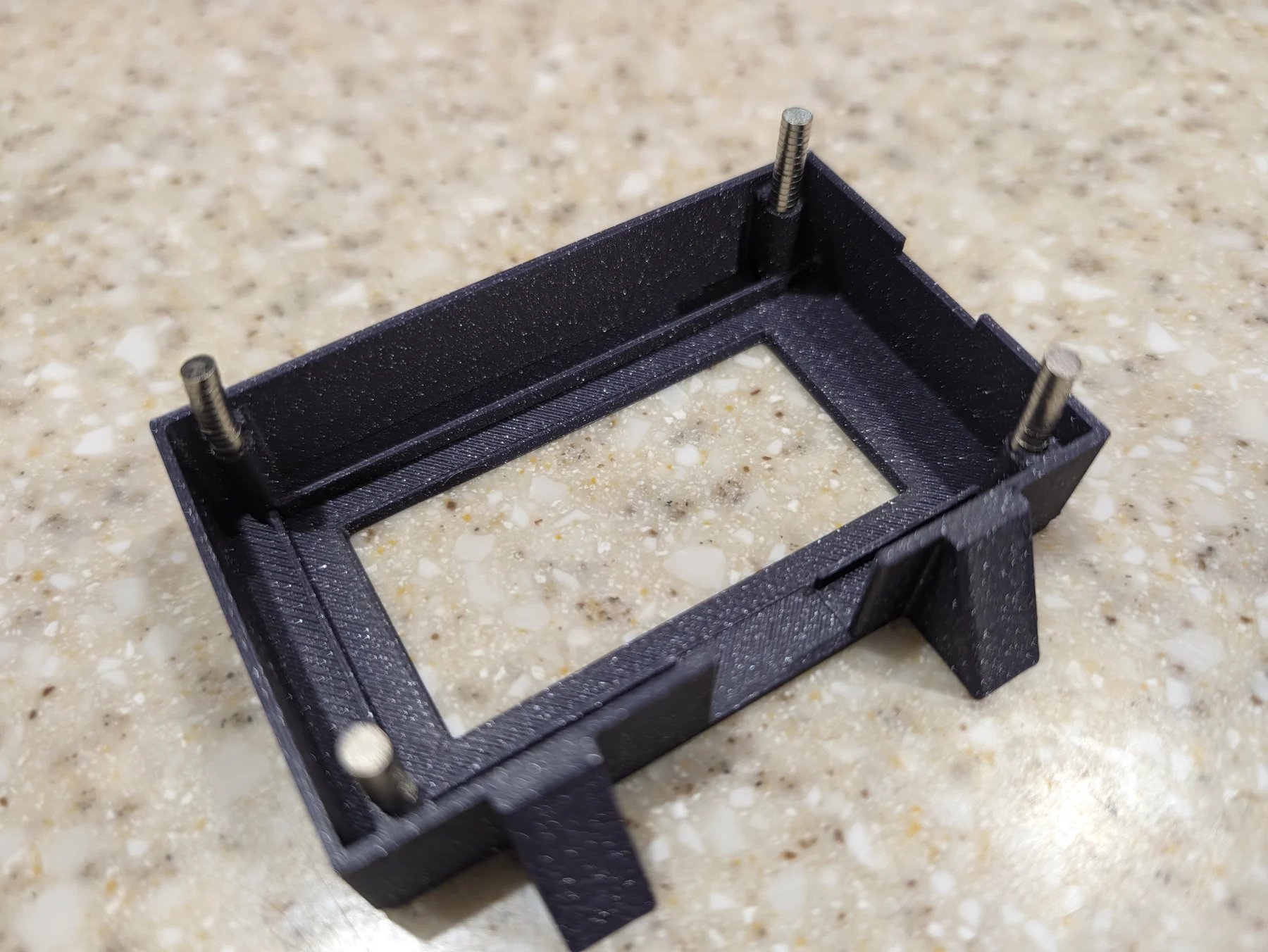
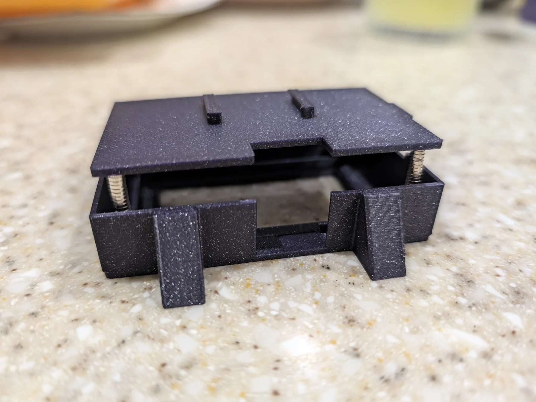
The third version used magnets, corrected the frame to 60 degrees from the desk, and angled the feet so the whole surface could make contact. I started with two diagonal magnet pairs. The enclosure weighed almost nothing. Surely two would be enough.
They were not enough.
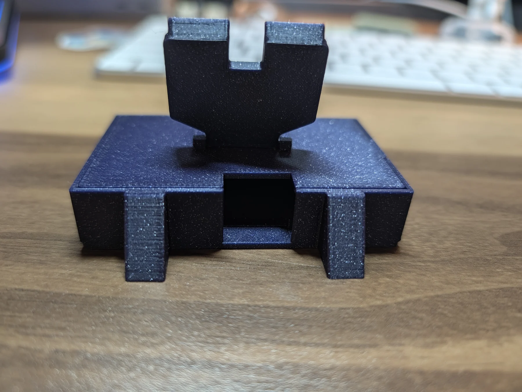
The bigger problem was depth. Product photos and a model of the board had given me an estimate. The delivered hardware had connectors sticking out of the back in several places. The backplate had no hope of closing, so I gave up on the limited Amazon product specs and pulled out the digital calipers. Here’s what I got:
- the device was 31.46 mm high;
- the tallest rear connector sat 11.51 mm behind the screen face;
- the right-angle USB plug made the connected assembly 38.03 mm high;
- the plug was 9.45 mm wide;
- the rearmost point of the connected plug sat 10.67 mm behind the screen face.
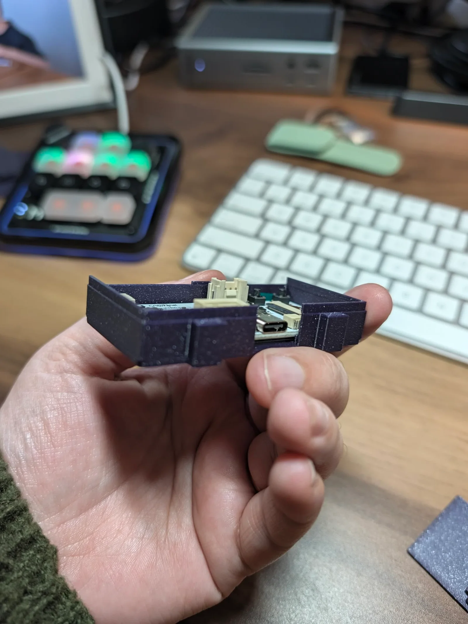
Those numbers changed the cavity, backplate, magnet pockets, cable tunnel, and rear leg. The board itself also became the truth source for the little internal shelves that keep the active screen aligned with the front opening.
V3 got the viewing angle right, but the rear cavity was too deep. The board could fall away from the face. The leg touched the desk on one corner instead of across its bottom surface, and the cable opening needed more height.
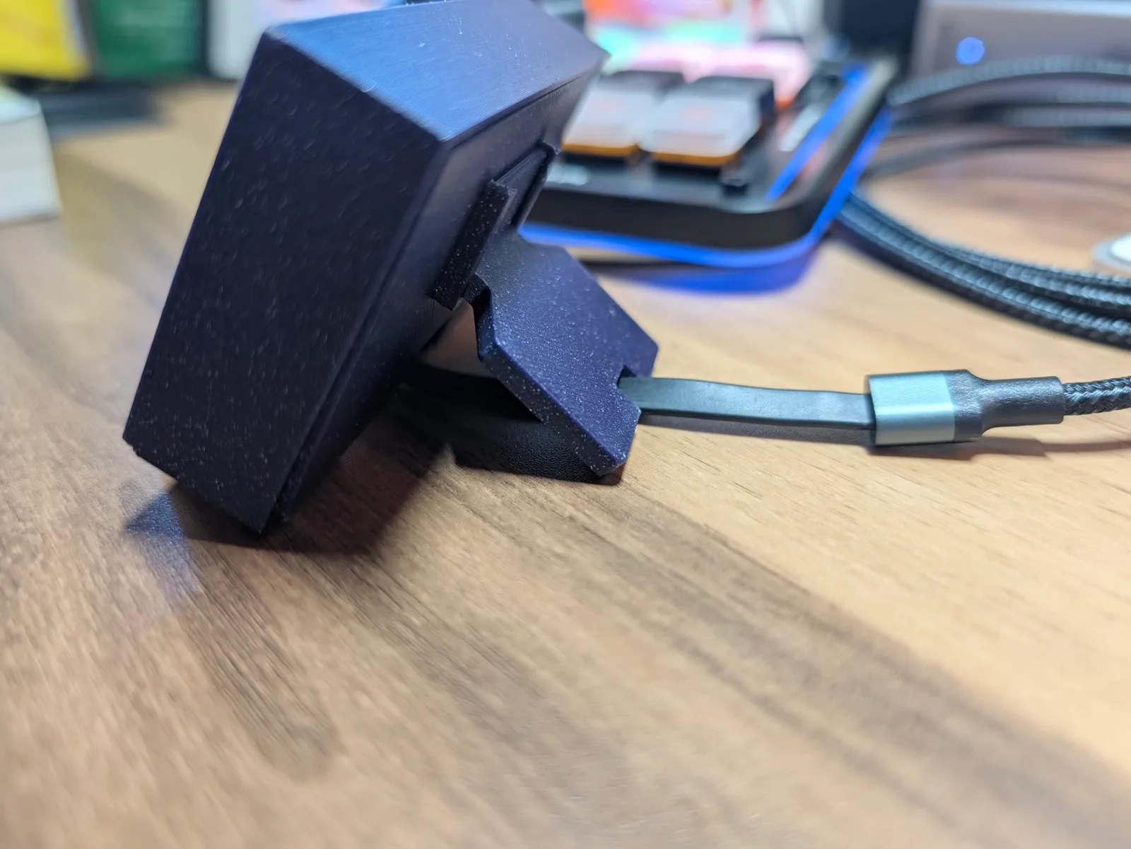
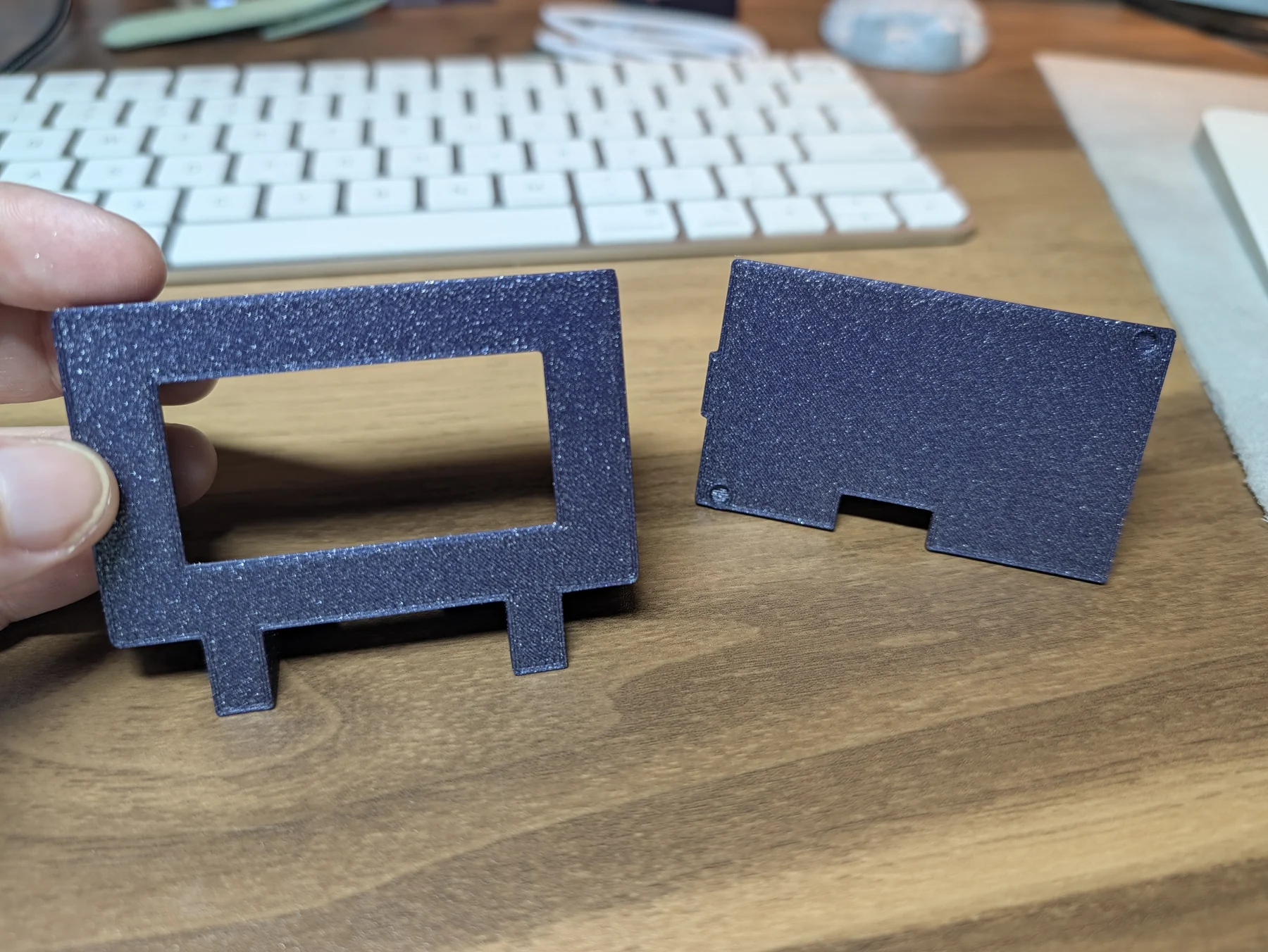
V4 fixed the depth, used four corner magnet pairs, enlarged the cable tunnel, corrected the front feet and rear leg for actual desk contact, and printed the visible face against a smooth plate. That was the first version where the object in my hands matched the thing I had been asking for.
The next adjustment had to wait while the P2S performed the more urgent work of producing an articulated great white shark skeleton for my son in gold filament. Product roadmaps contain multitudes.
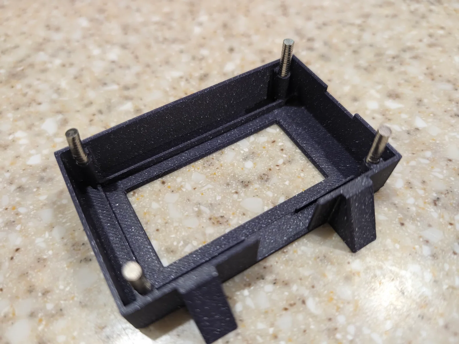
The remaining fit problem was comically small. A folded strip of Post-it behind the board supplied enough pressure to keep the display exactly flush with the front window, but it also pushed hard enough to weaken the magnetic closure.
The printed V5 backplate adds 0.16 mm of rigid preload, one printed layer, in place of the paper shim. The front frame, leg, angle, cable path, and visible design stay exactly the same.
Print the enclosure
You can download the enclosure from Printables or MakerWorld, or use the source and meshes in the GitHub repository’s enclosure directory. The downloads include individual STL files, parametric OpenSCAD source, a magnet fit gauge, and a Bambu Studio project. The marketplace downloads include the complete three-part project; the GitHub 3MF is a replacement-backplate project for an existing build.
Print one of each:
- frame;
- backplate;
- rear leg.
The tested Bambu Lab P2S settings are:
- 0.4 mm nozzle;
- 0.16 mm layer height;
- 0.20 mm first layer;
- three walls;
- 15 percent infill;
- supports off;
- auto brim;
- 0.15 mm elephant-foot compensation;
- PLA Sparkle.
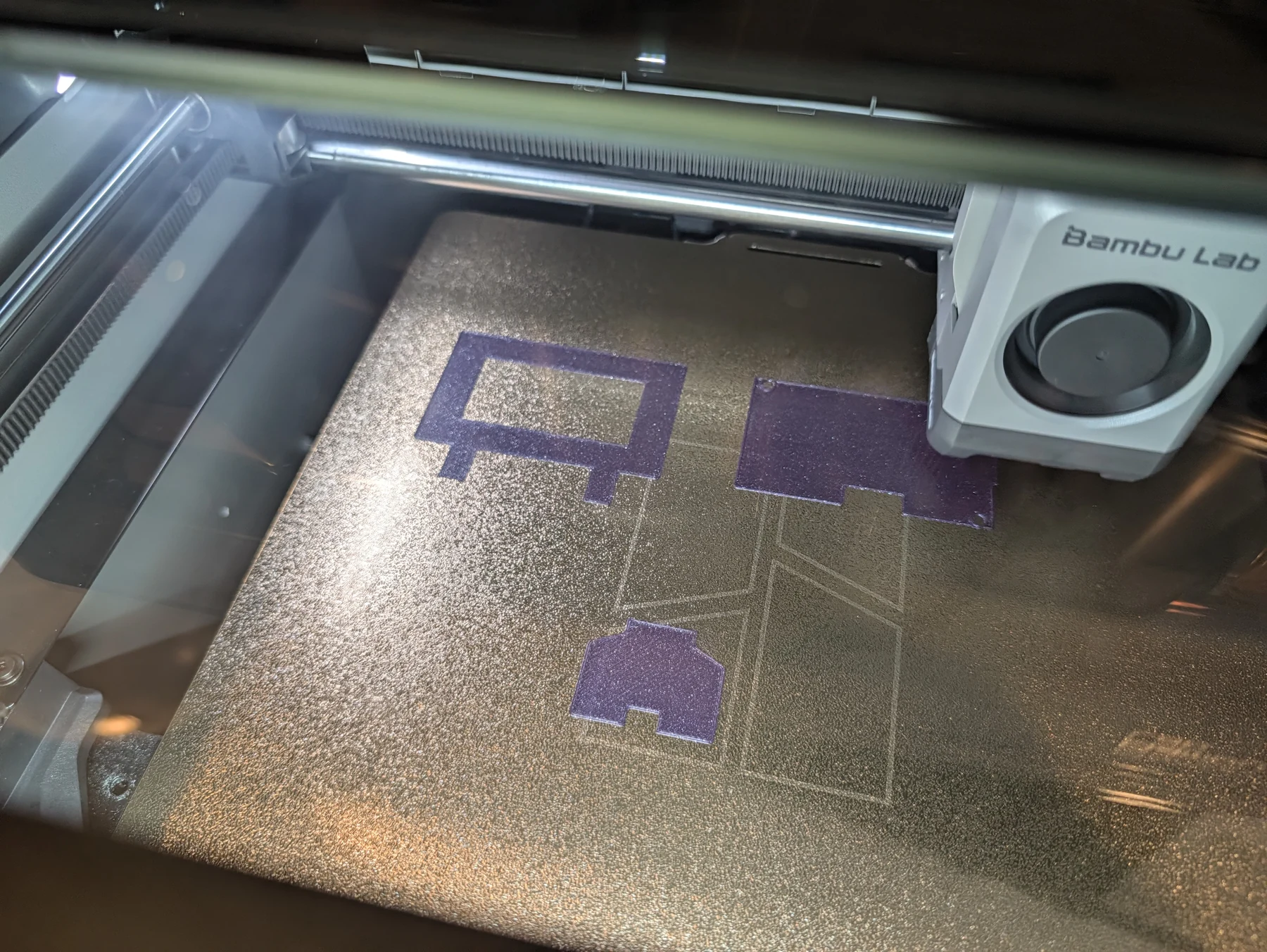
Print the frame with the front face directly on the plate. That gives the visible bezel the plate’s finish. I tried both textured PEI and smooth PEI and my final build uses the smooth option.
Assemble it without gluing yourself to the front
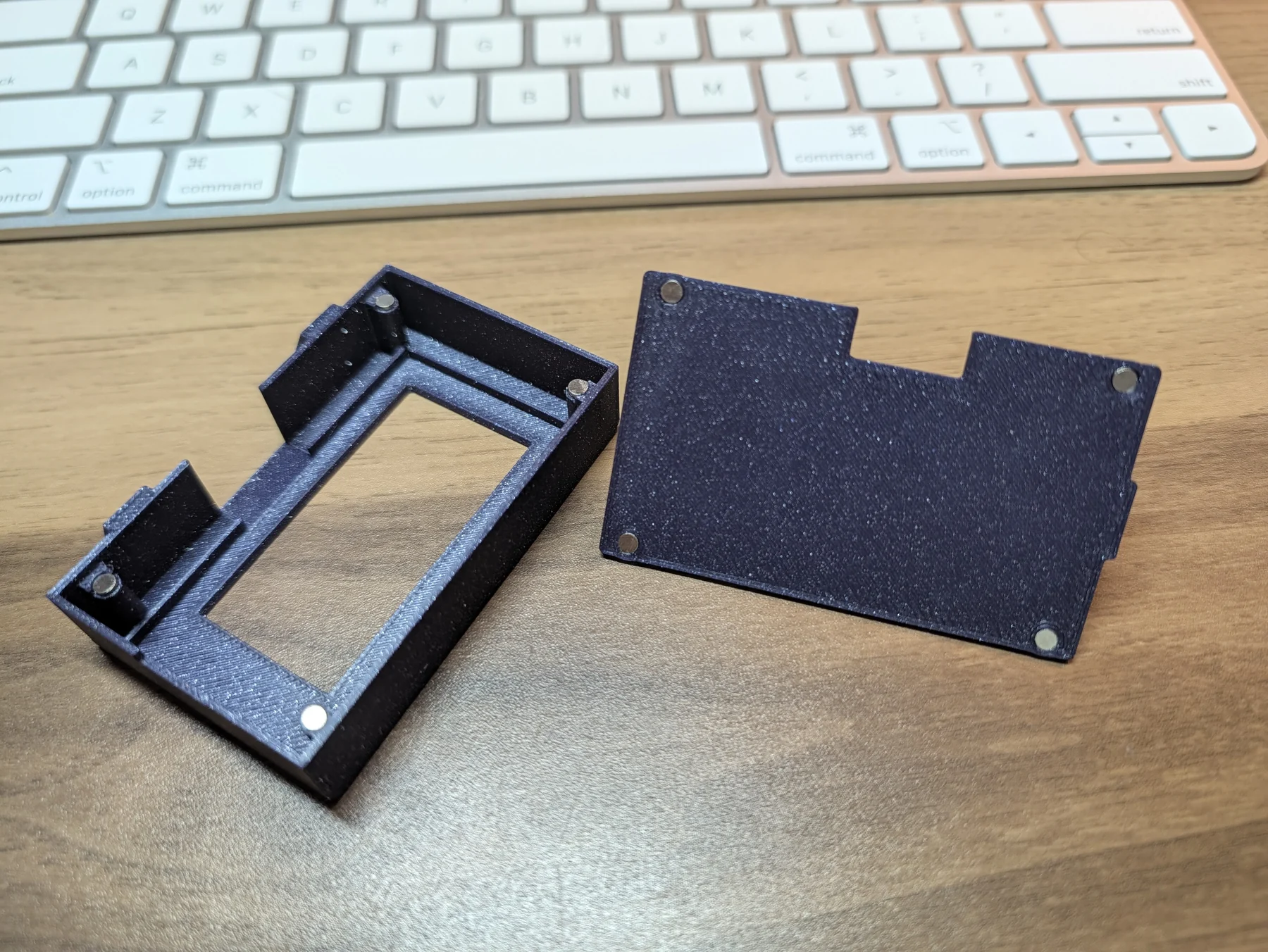
The enclosure uses four magnet pairs: four magnets in the frame and four matching magnets in the backplate.
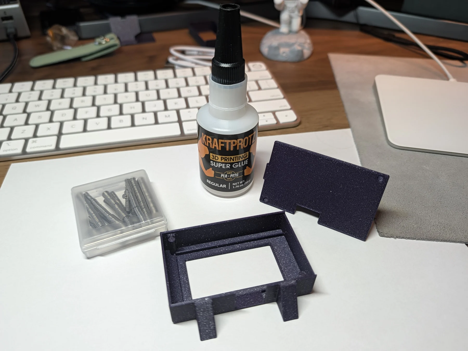
Before glue enters the conversation, dry-fit every magnet and mark the mating polarity. These magnets are tiny and astonishingly committed to escaping. Work over a tray.
Then:
- Glue the four 3 × 1 mm magnets into the frame pockets.
- Glue their four mates into the backplate pockets.
- Let the cyanoacrylate cure fully.
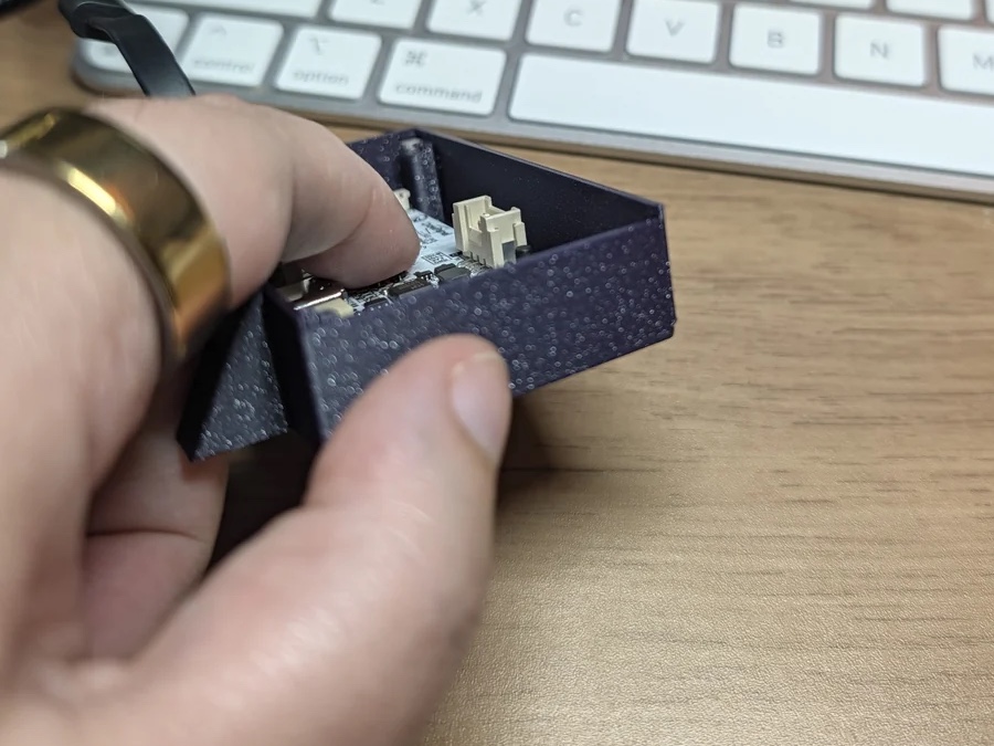
- Plug the right-angle USB-C connector into the display, with the cable aimed through the bottom tunnel.
- Seat the CrowPanel from the rear against the front opening.
- Place the backplate straight into its recess so all four pairs meet.
- Slide the rear leg into its socket.
- Route the cable so it isn’t trying to drag a roughly 20-gram object around your desk.
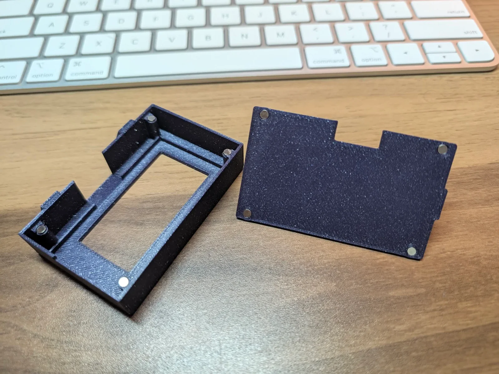
I got superglue on one visible frame during testing. That print became my sacrificial fit model, and my model-builder husband stepped in to handle the final magnet installation on the final version. Every household needs a closer.
Troubleshooting the failures I actually had
| Symptom | What was happening | What to check |
|---|---|---|
| The display still shows an old percentage | The service stopped, the Mac slept, or USB disconnected | Read LAST REFRESH, then inspect health.json and the launch agent |
| The screen becomes static or strange glyphs | The e-paper initialization or waveform files do not match the tested build | Re-run the pinned firmware preparation and flash the tested firmware |
| The percentage sign looks wrong | The font asset or glyph renderer does not match | Use the repository’s generated font and firmware |
| The host cannot find the board | The cable has no data connection, several bridges are attached, or the transport config is wrong | Use one known data cable, run probe-chip, and check the USB identity |
| The screen clears when it reconnects | Firmware is replacing the retained frame before it has valid data | Use the repository firmware, which waits for a valid message before redrawing |
| The enclosure will not close | The panel, cable, magnets, print scale, or enclosure version differs | Confirm the exact parts and print at 100 percent scale |
| The panel sits behind the front window | The rear cover is not supplying enough preload | Use the final backplate with the 0.16 mm correction |
Project links
- Code, firmware, Mac service, and OpenSCAD source on GitHub
- Printable enclosure files on Printables
- Bambu Studio project and print profile on MakerWorld
- Elecrow 2.13-inch ESP32 e-paper CrowPanel
- Right-angle USB-C data cable
- Magnet assortment containing the tested 3 × 1 mm discs
What working with AI actually looked like
Codex did most of the implementation. It turned the screen brief into mockups, wrote the Mac service and ESP32 firmware, built a USB protocol, generated a bitmap font, inspected hardware documentation, modeled the enclosure in OpenSCAD, produced STLs and Bambu projects, and kept enough notes that I can now reconstruct this entire slightly unhinged process.
At various points, it also made the display portrait when I wanted landscape, designed an unexplained shoulder into the frame, and made the stand lean the wrong direction. It created a PLA latch that blocked the part it was supposed to retain, then snapped when asked to flex. It trusted nominal geometry until the real board proved that the cavity was several millimeters too shallow. It gave me a percent sign that was first clipped, then visually louder than the number, then briefly replaced by gobbledygook.
Every failure narrowed the next problem, and my job was to simply repeat the same deeply unglamorous loop:
- Say what the thing needed to do.
- Let Codex make a candidate.
- Inspect the actual output.
- Touch the physical object.
- Name exactly what failed.
- Measure whatever I’d been guessing about.
- Change the next version around that evidence.
Each judgment changed the engineering. That was taste doing an actual job.
The whole build, in order
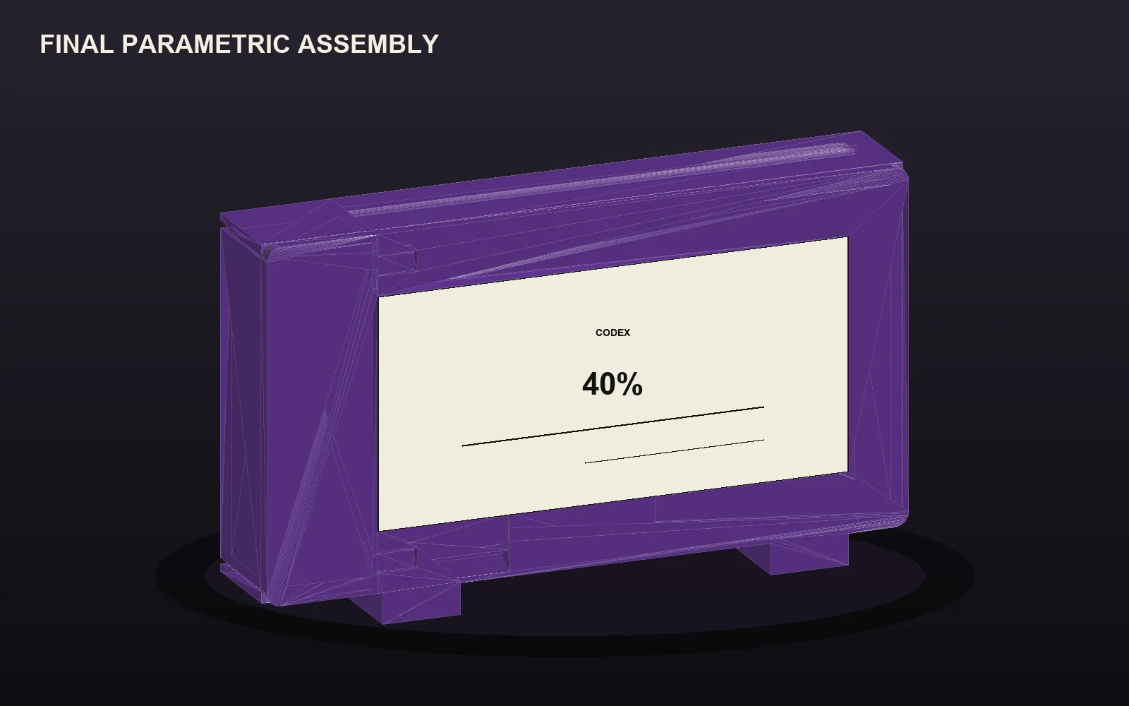
The finished display is so small and tidy that it conceals how many distinct versions had to be wrong first. This is the complete visual record, trimmed to one clear image for each meaningful design change, print run, fit problem, and assembly step.

Apparently, this is why I understand developers
Like I said at the beginning, people have asked me for years now how I learned the developer persona so well.
I never had a satisfying answer because “developers” aren’t one personality type. They’re just smart people who build things, right?
This project gave me a better answer.
What I understand is the itch. A stupid little friction point gets under your skin, so you open the machinery. You distrust the green checkmark when the real thing still feels wrong. You keep pulling on one bad assumption until the system tells the truth. And what’s DevRel? It’s just writing down what you learned so the next person doesn’t have to step on the same rakes you did.
My strongest expertise is content, product judgment, developer marketing, and communication. Codex supplied most of the coding and a large amount of the mechanical implementation. Alex supplied magnet-installation competence. The Bambu supplied a small parade of purple plastic evidence. All of those specialties ended up in the same tiny object.
That combination is what I have always loved about good DevRel. Someone starts with a real problem, makes a useful thing, tests the promise instead of admiring the machinery, then explains the expensive parts so the next builder gets a cleaner path.
So, no, I never reverse-engineered a developer persona. I recognized the builder instinct because it was already mine.
Now the answer sits under my monitor: one number, six days until reset, last refreshed a few minutes ago.